|
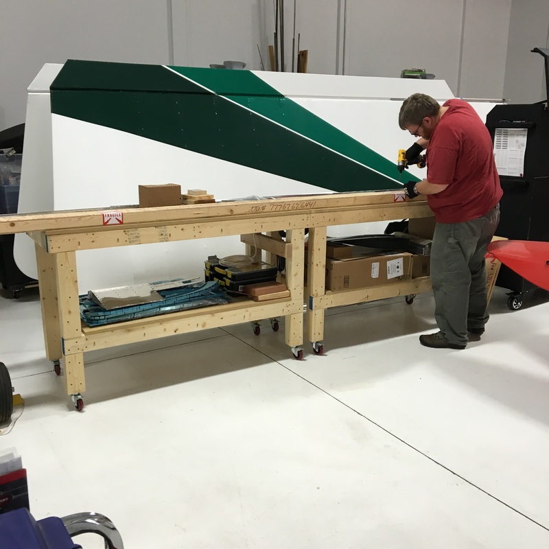
We finally received our replacement parts. Of course, they arrived the day before we left on vacation. All we managed to do before our trip was deliver the parts to the hangar and inspect them for damage. I really admired the beautiful crate that someone built to get them to us in one piece. And, thankfully, the freight didn't cost as much as expected. Now, we can get back to work!
0 Comments
Absolutely no progress has been made on the plane lately. We're still waiting for the replacement parts from our major mistake a few weeks ago. There was a little miscommunication when Mike placed the order and Van's was holding the parts for us to pick up at their Oregon factory. Once we got that sorted out, it still takes another week to get them shipped to us. The parts themselves only cost about $75 to replace plus $15 to have them crated , but the freight is another story. We won't know how much is costs until we pick up the crate, but Mike is estimating $250 for shipping. Ouch! Let this be a reminder to always read and reread the directions!
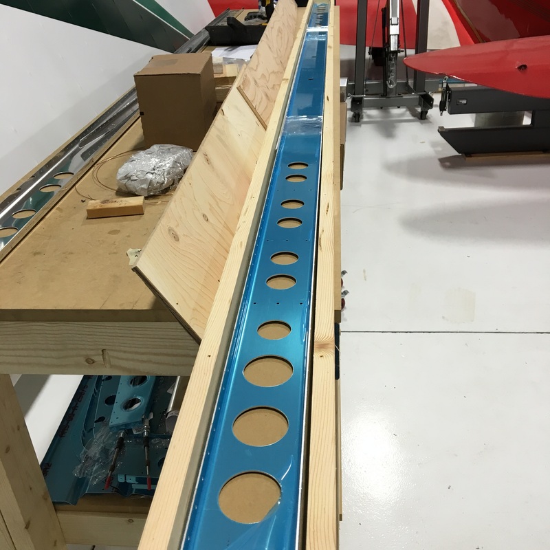
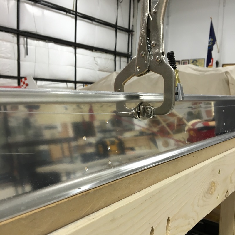
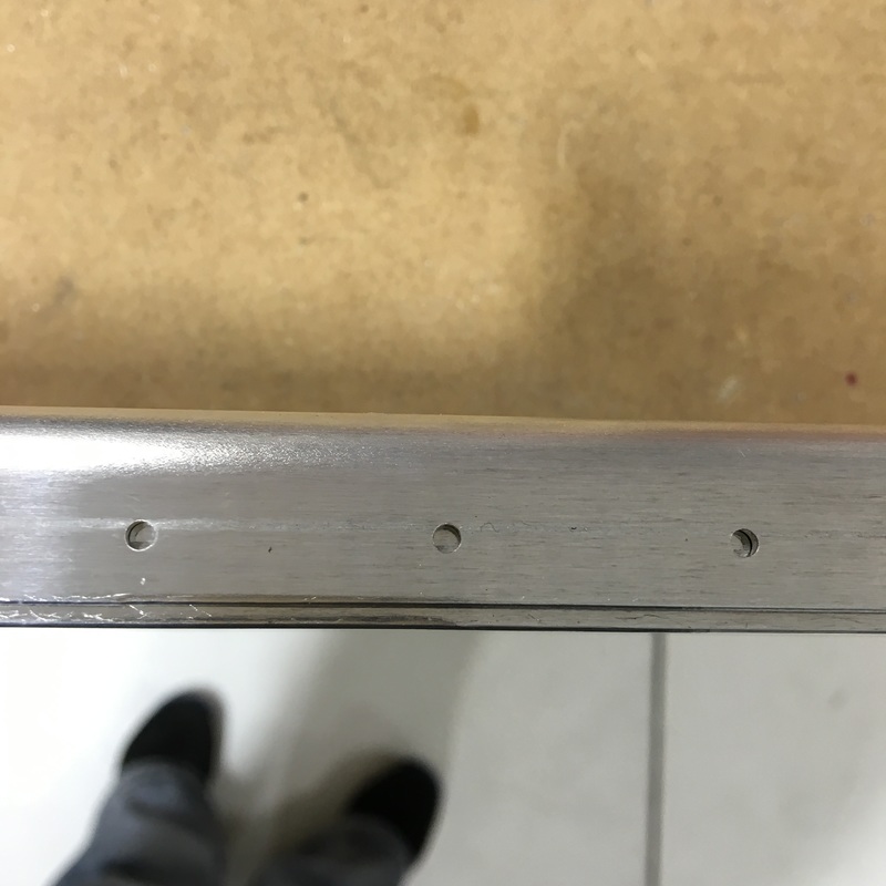
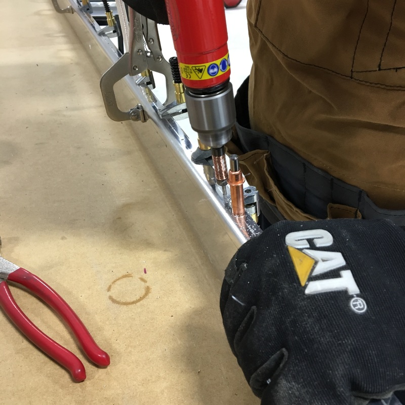
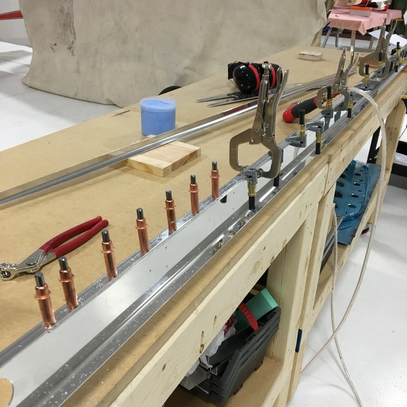
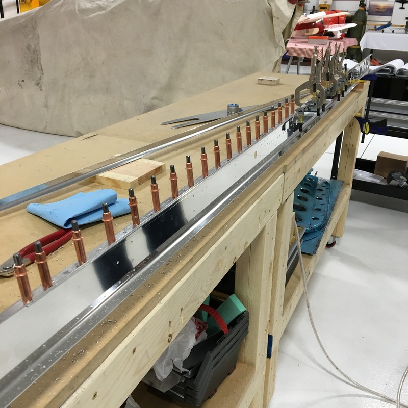
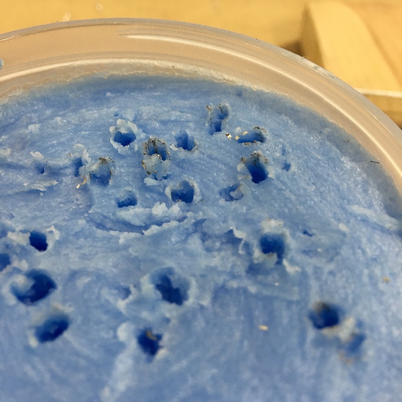
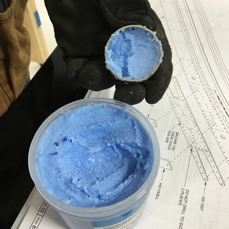
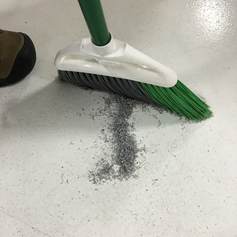
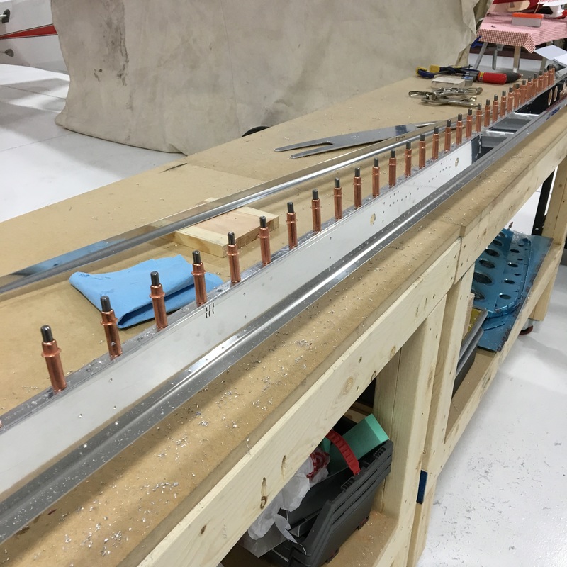
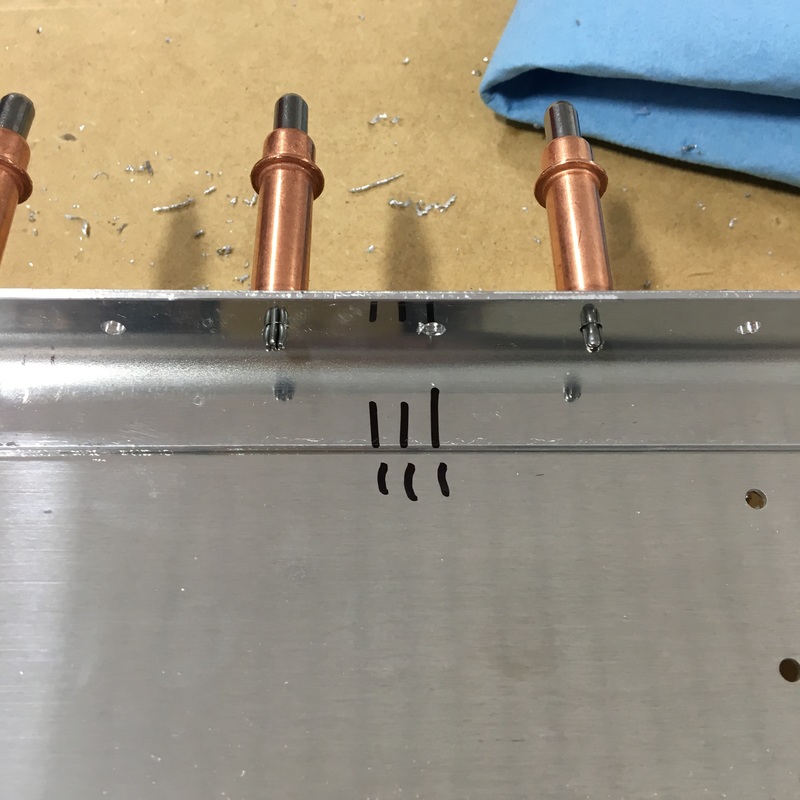
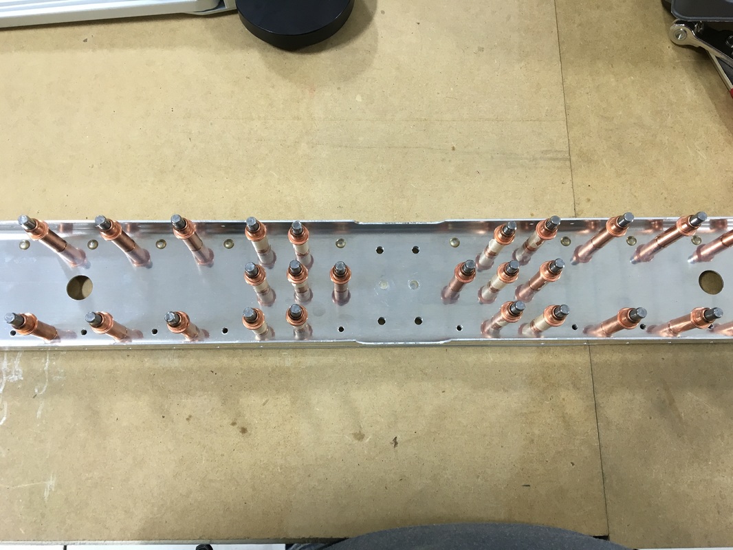
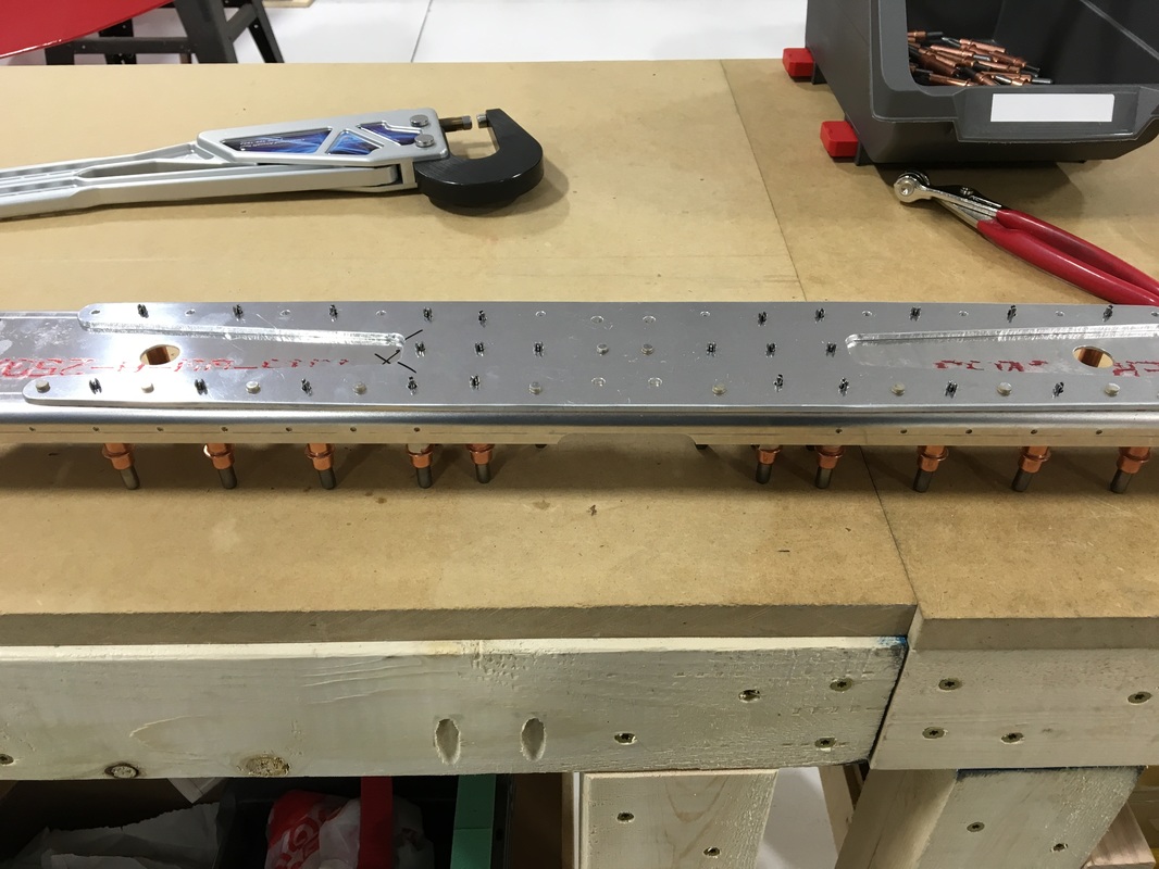
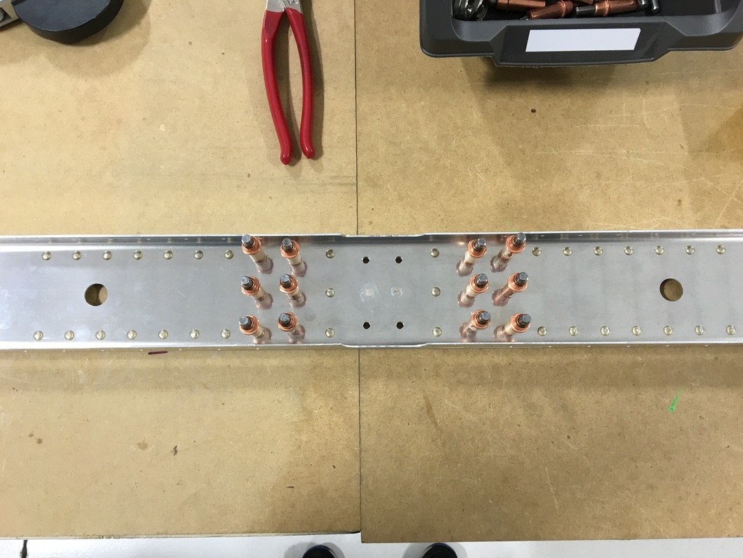
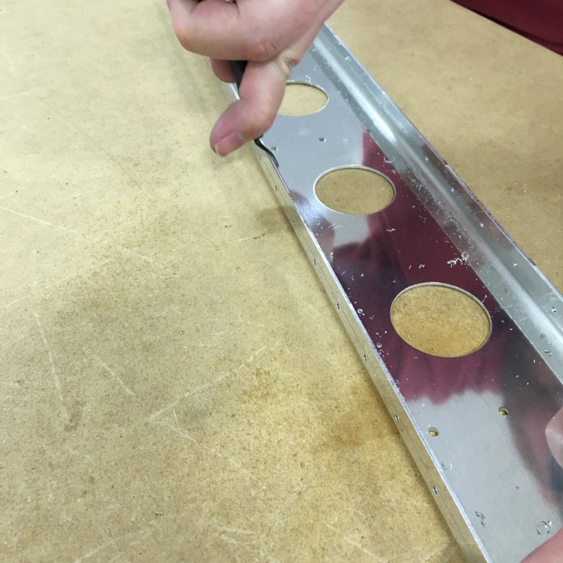
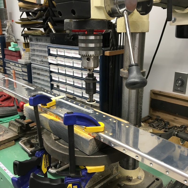
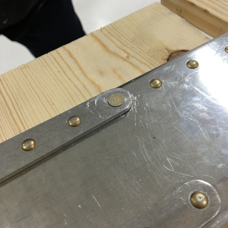
I spent the first part of today doing something that I've accepted is a big part of airplane building - deburring. We call it making glitter because you end up with a nice little pile of aluminum shavings that looks something like this... 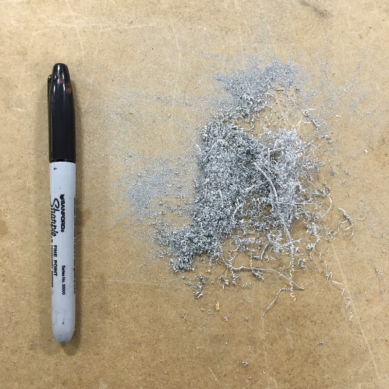 I'm getting much better at deburring. Mike says those tight spirals (like the long one on top of the pile) are a sign that I'm doing something right. (The sharpie has no significance, it was just the first thing I could find to provide a sense of scale). I've figured out how to use the different deburring tools and I have my own little system that I work through on each piece. I'm also getting very good at removing tiny aluminum slivers from my fingers. When you deburr, you run your finger down the edge to make sure that it's smooth and I usually pick up half a dozen slivers over the course of a day. I've tried wearing gloves with mixed success when I deburr. The gloves protect me from tiny metal shavings but can also make it harder to tell if I've done a good job. Some gloves also leave lots of fuzz on the edge of the pieces that I then have to clean off. I'm experimenting with different types of gloves to find something that will work. So far, rubber coated gardening gloves seem to work pretty well. I only wear the left glove while I work, and since my gloves are blue I feel like a smurfy Michael Jackson. By the way, all those shavings came off these six parts. 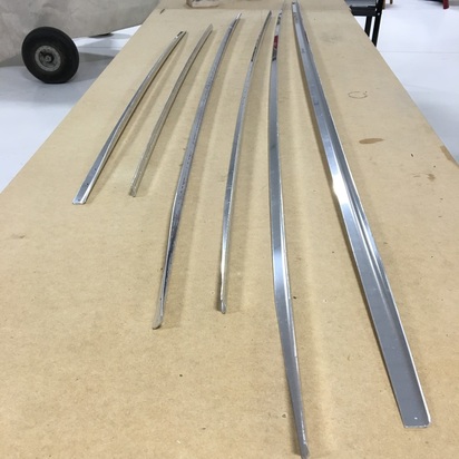 These parts are called caps, although I'm not sure why, because they don't go on top of anything. They actually fit inside some of the long aluminum spars, I suppose to provide extra strength. It's very hard to see in this picture, but Mike had to very carefully cut a small angle off the ends of each of these spars. Again, I have no idea why that's a necessary step but I guess I have to trust that there's a good reason for it. The two longest pieces are part of the front horizontal spar. The cap nestles inside the spar and holes need to be drilled along it's length so the whole thing can (eventually) be riveted together. There are no holes in the caps so everything has to be held together with clamps while we drill. As we drill holes, we can insert clecos to keep things in proper alignment. The cap doesn't extend the entire length of the spar, and it needed to be installed in a very specific location. To get the cap perfectly centered, we had to make a mark 1/4 inch from the ends of the cap. We then lined up that mark with the center of the 33rd hold from each end of the spar. We were very careful and checked each other's work before we proceeded. The last thing we wanted was to align the cap improperly and mess up the holes. Once we had everything lined up, Mike drilled holes while I moved clecos and clamps. We had a very good system and worked really well as a team. There were probably about 40 holes that needed to be drilled on each spar and with Mike running the drill while I moved clecos it went surprisingly quickly. All the drilling created A LOT of metal shavings. Mike was using the blue Boelube on the drill bit and we quickly realized that the metal shaving were going to cause a problem as they built up in the Boelube container. We got a smaller container and put a small amount of lubricant into it so we wouldn't contaminate the entire jar. I also took a picture of the metal shavings we swept up after drilling one side of the spar. Once we had the first side drilled, we took everything apart so we could flip it over and work on the other side. Before we dismantled everything, we made sure to mark both the spar and the cap we had just drilled so we could easily line them up later. Drilling the second side went even faster, at least until we were about 10 holes from the end. It was at this point that we stopped to consult the instruction manual to see what we would be doing and things began to go terribly wrong. When we checked the instructions, this is what they said: 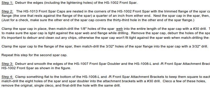 OK, so I admit I'm kind of messing with you. There's no reason any of that should make sense to you, but I want to show you an example of the kind of directions we are working with. They are very densely written and each "step" in the instructions can actually include anywhere from 1 to 10 individual steps. All of these individual steps are then written in the form of a paragraph, just to make everything even more annoying. Sometimes a single sentence in that paragraph will include more than one step. Here, let me highlight the really important part of that set of instructions. 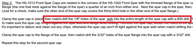 Let me explain why that line of instructions was such a problem. To do so, I'll have to explain some vocabulary that I've been ignoring so far because it seemed overly technical. Actually, a picture will probably explain it better than I can in words... 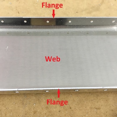 The web is the wide flat part and the flanges are the narrower bits that are bent at a 90 degree angle. If you look back at the line of instructions I highlighted, we were supposed to be drilling holes in the web, which is most definitely NOT what we were doing. The fact that they even underlined the word "web" tells me that we're not the first ones to make this mistake.
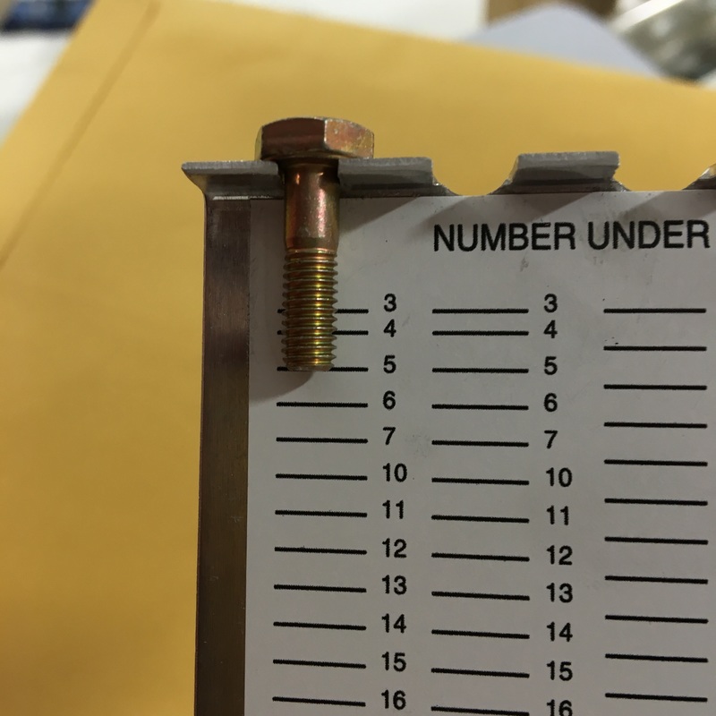
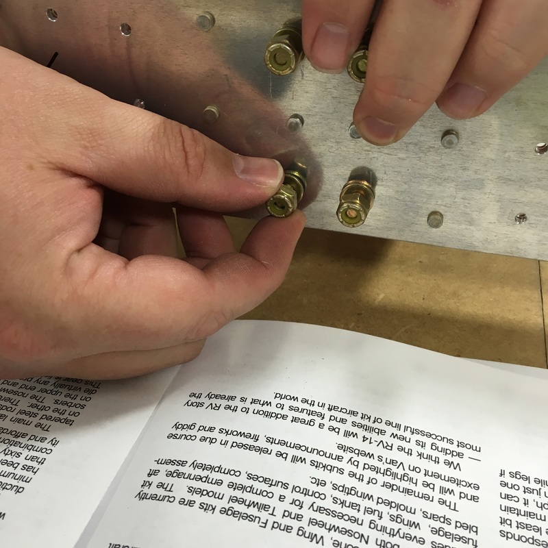
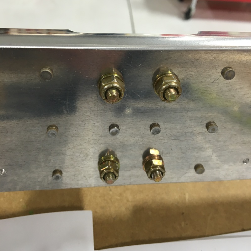
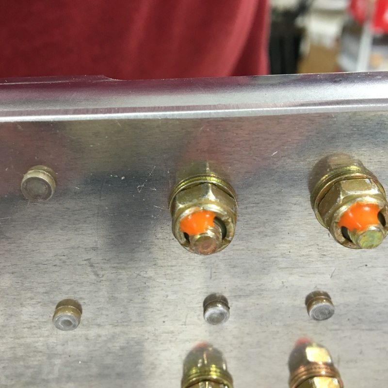
You might say, "So, what's the big deal, the next line of instructions says to drill holes in the flange." The problem is that those holes are two different sizes. The holes we drilled are 1.5 times the diameter they were supposed to be and will eventually be used to attach the skin to the spar. The fact that they're too big is a major problem because the skin has to be dimpled and the aluminum on the skin just isn't thick enough to be dimpled quite that much, then riveted with bigger rivets. We even contacted the kit manufacturer to see if there was any possible way we could make it work. They (not surprisingly) said there was no way to salvage it. So, we drilled the wrong size holes in the wrong place and basically the whole part is now scrap metal. We contacted Van's to order replacement parts (the front spar and the two caps). Since the spar is 13 feet long, it has to be crated and shipped by freight truck. The crating and freight alone cost more than $100. When we tally up the total damage, our mistake cost us about $150 and wasted about 6 hours of work. Honestly, we're dealing with this whole mess pretty well. We were disappointed when we realized how badly we'd messed up, but what are you going to do? Afterward, we talked about how we could have misread the instructions so badly. I fully admit that because the instructions were so densely worded, I got lazy and didn't read them very carefully. Mike seemed to know what he was doing so I just went with it rather than reading and understanding the instructions myself. I think Mike simply read through the instructions too quickly and missed that crucial wording. The silver lining to this whole mess is that every time we make a mistake, we work out a system to avoid that particular mistake in the future. Once we get our replacement parts, we can figure out how to navigate these instructions better and (hopefully) save ourselves some heartache in the future. I don't know who writes the instructions for these airplane kits, but I have a distinct feeling that they prioritize technical details over clear communication. Today, I'd like to tell you the saga of installing 4 bolts on the rear spar of the horizontal stabilizer. You might recall in my last post that there was a part I didn't know the name of and didn't know what it did. Well, I still don't know what it is or what it does. I keep meaning to ask Mike about it, but I always forget and he's never around when I'm writing these posts (he's currently at the hangar working on installing our new shelving).  Mystery part This is the first part that gets bolted onto the plane rather than riveted. You might think that installing 4 bolts would be an easy process, but you've never read an airplane kit instruction manual. I'm going to walk you through this step-by-step so you can fully share in the experience. I feel like I should warn you that this post in an exercise in vertical scrolling. Step 1 - Consult the diagram to find out the part numbers for the bolts you need. (Also, I guess the mystery part is called the "inboard hinge bracket assembly" but I still don't know what it does.) 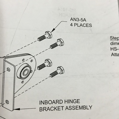 Step 2 - Locate part number AN3-5A on the inventory list and identify which bag of parts to look in. 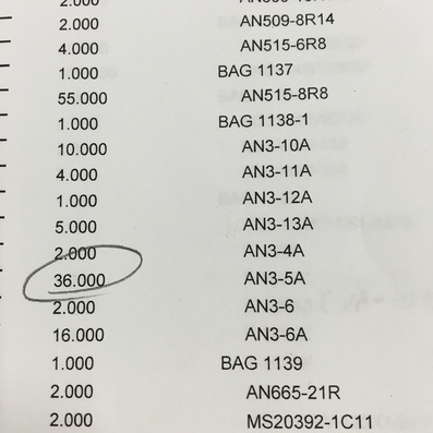 Step 3 - Find Bag 1138-1. 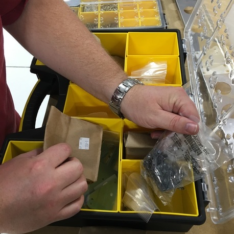 Bag 1138-1 contains a whole bunch of different sized bolts 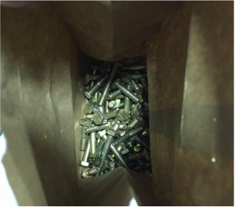 Step 4 - Find the right size bolt using a bolt gauge. You use the top notches to find the diameter of the bolt, the first slot is for size AN3. Then the horizontal lines tell you the length, this is a number 5. Step 5 - Refer back to the diagram to find out what size washers and nuts you will need. 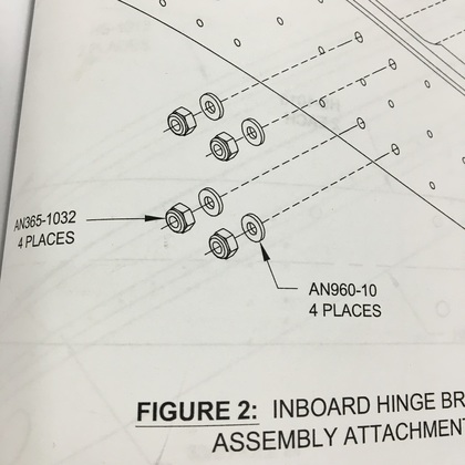 Step 6a - Go back to the inventory list and find washer number AN960-10. Step 6b - Look through the entire 6 page list three times because you can't find the part number. Step 6c - Realize that they've changed the part number and you needed to be looking in the Description column this whole time. The AN960-10 washer is now a NAS1149F0363P washer. 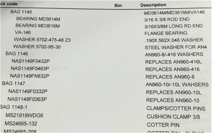 Step 7 - Find bag 1147. Step 8a - Discover that bag 1147 contains two, nearly identical types of washers. Step 8b - Realize that when we counted every single item on this list that we should have separated and labeled all the hardware. Step 8c - Figure out which washer in the bag is which. Can you tell the difference? 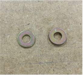 Here's a different picture that makes the difference more obvious. 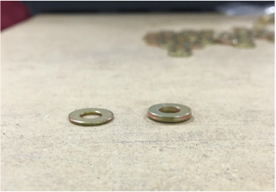 Step 9 - Find the right size nuts (AN365-1032). I didn't take any pictures of that because I was either really sick of the whole process at this point and/or because they were surprisingly easy to find. These bolts have to be tightened very gently to a very specific torque (they can't be too tight or too loose), which leads to step 10... Step 10 - Refer to the next step in the instruction manual that tells you how much to tighten the bolts. Or, more specifically tells you where to find that information. 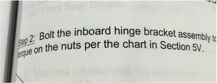 Step 11 - Refer to Section 5V... 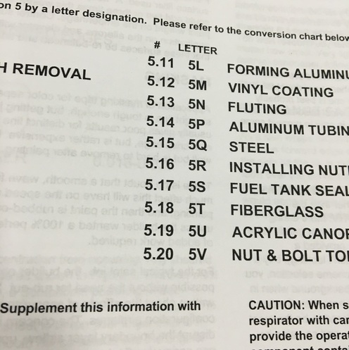 Which refers you to section 5.20, that you actually find on page 5-18... 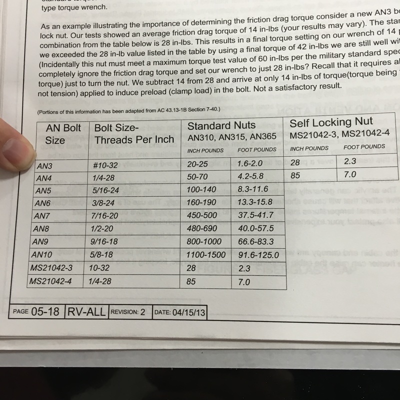 Where you read this chart... 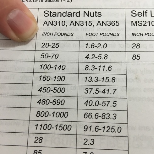 By locating the right size nut (remember is was an AN365-1032) to find out that it should be tightened to 1.6-2.0 foot pounds. Step 12 - Celebrate that you've finally found all the parts and information that you need to install 4 freaking bolts! Step 13 - Actually install the bolts, using the ridiculously expensive torque wrench you had to buy for this one specific job. This step will take about 2 minutes. Step 14 (Optional) - Put torque seal on the bolts. Torque seal is this orange paint-like stuff that makes it a lot easier to inspect this bolts later and make sure they haven't tightened or loosened. If the paint glob is intact you know everything is fine, if it's broken you know you need to do some maintenance work. Step 15 - Put away all of the crap that you had to dig out to do 2 minutes of work.
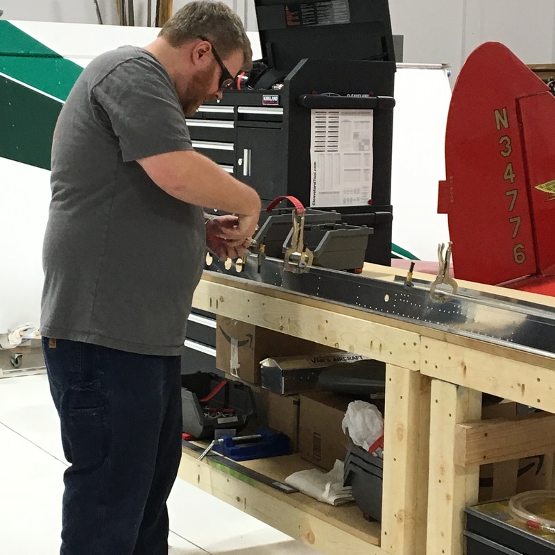
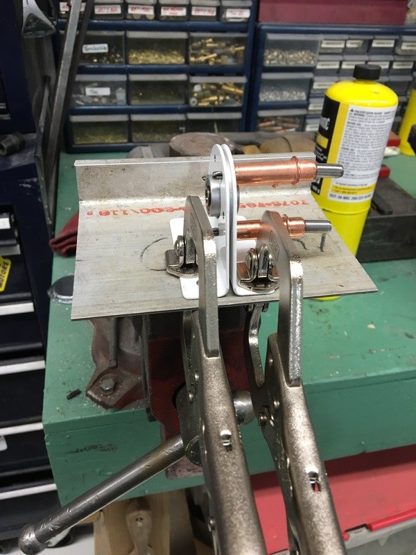
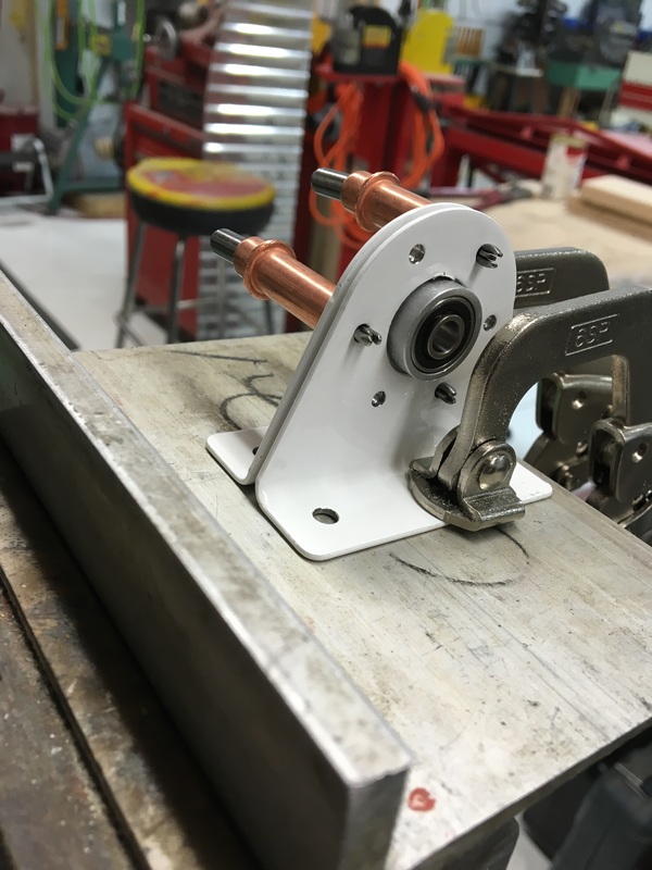
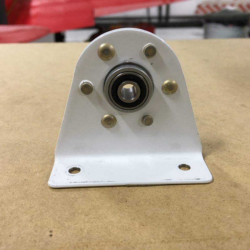
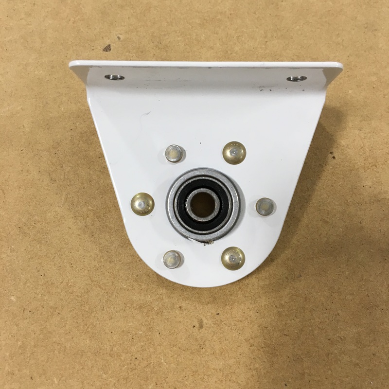
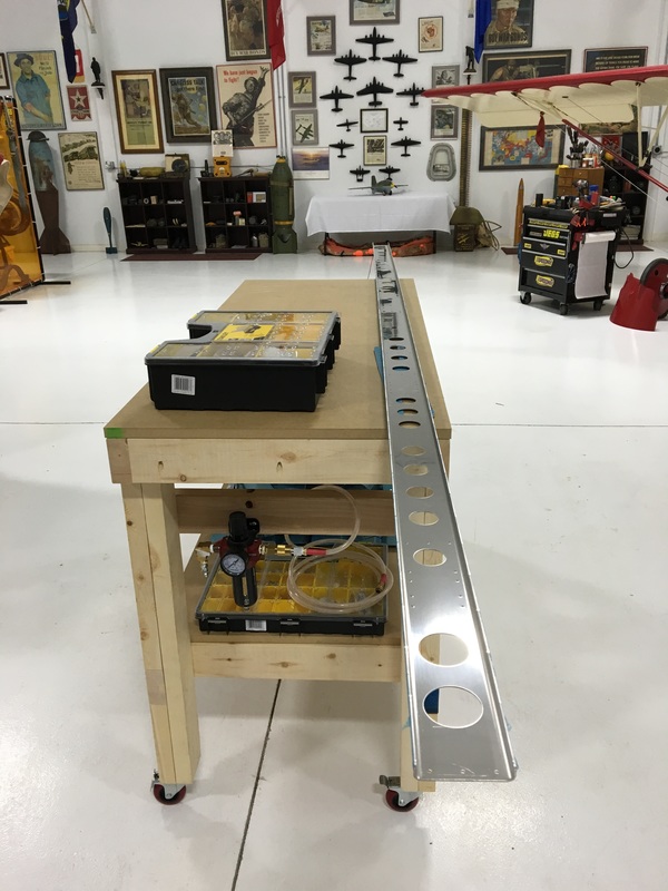
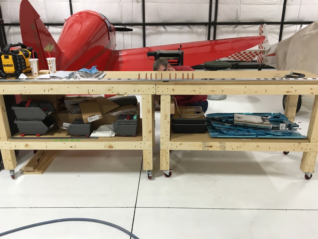
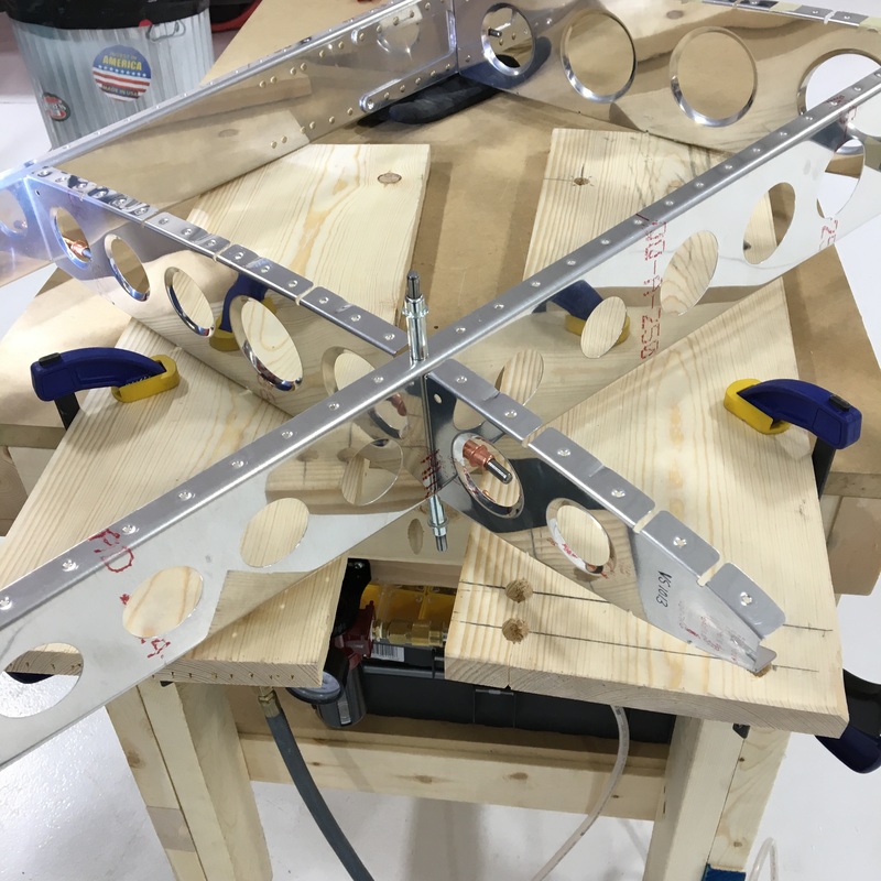
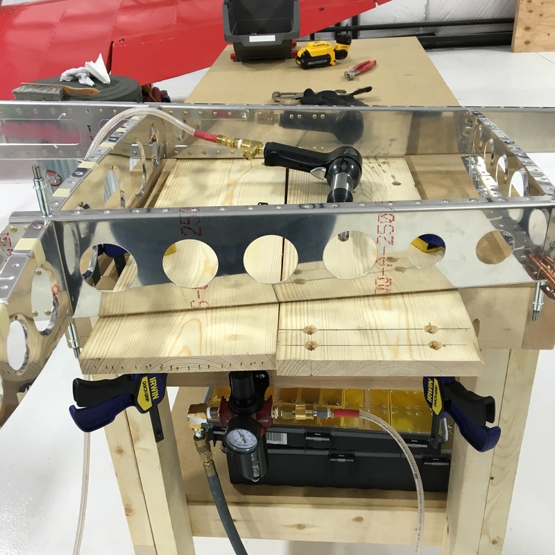
Work continues on the horizontal stabilizer but lately we've spent a lot more time getting organized than actually building. We are constantly accumulating supplies and finished pieces like the vertical stab need to be safely stored out of the way. Mike and his buddy, Keith, spent an entire day travelling to my hometown to pick up some old shelving so we can have a better place to store parts at the hangar. They also picked up this... 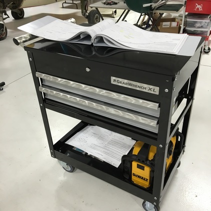 I never expected to be so excited about a tool box, but now we can finally get some stuff off the surface of the workbench. That has made working on the horizontal spar much smoother. The horizontal pieces are so long that they still hang off the ends of the clamped together workbenches so we need all the work space we can get. 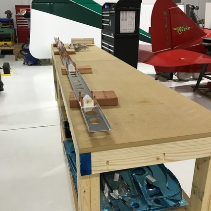 Mike finished the prep work on the doubler for the horizontal spar. The doubler is a thick piece of aluminum that provides structural support in the center of the spar. We've been using the squeeze riveter because once you get the gap on the riveter set things go really quickly. It's hard to see, but the clecos that are remaining in the bottom left picture have masking tape on them, which is our reminder that those holes will stay empty. I'm not sure what those empty holes will eventually be used for, but I would guess that they will be used when we put the whole vertical stabilizer skeleton together. That's the problem when I don't got up to the hangar for a few days - I don't have a chance to ask Mike questions about what we are doing and why. That also explains why I have no explanation for the next piece that we put together. I have absolutely no idea what that is - other than that there's some sort of bearing in the middle that turns and it's part of the tail section of the plane. I'm sure it's very important and that I'll eventually find out.
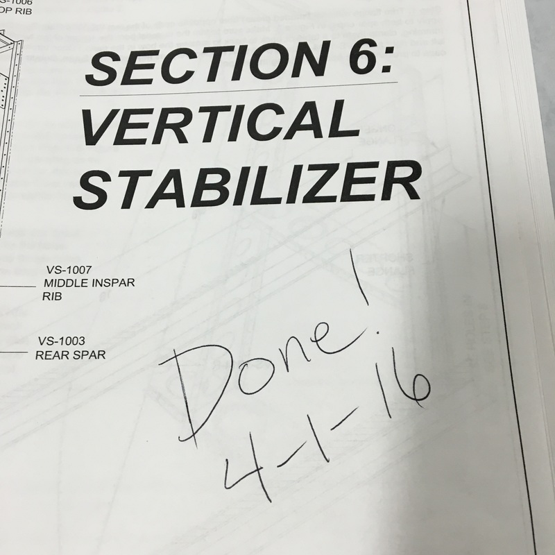
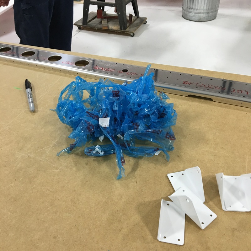
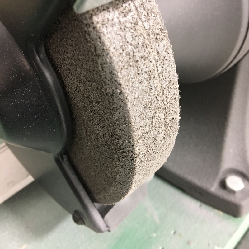
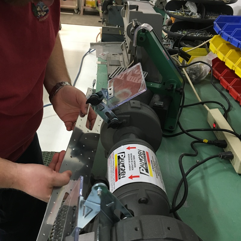
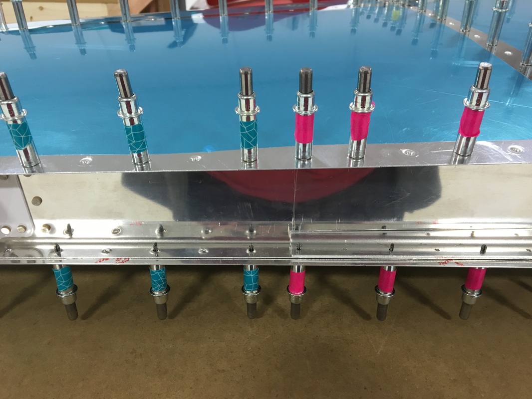
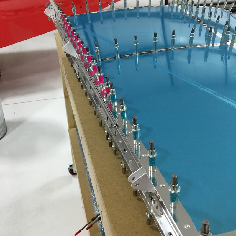
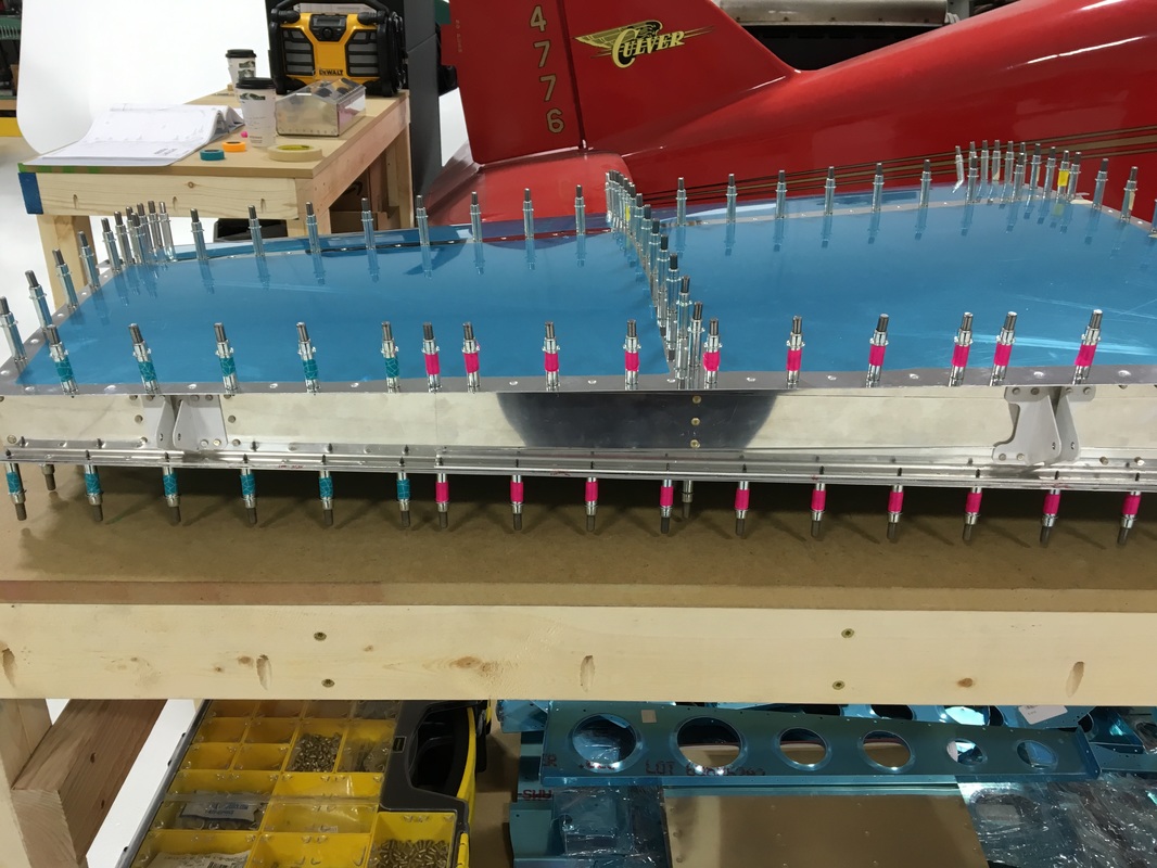
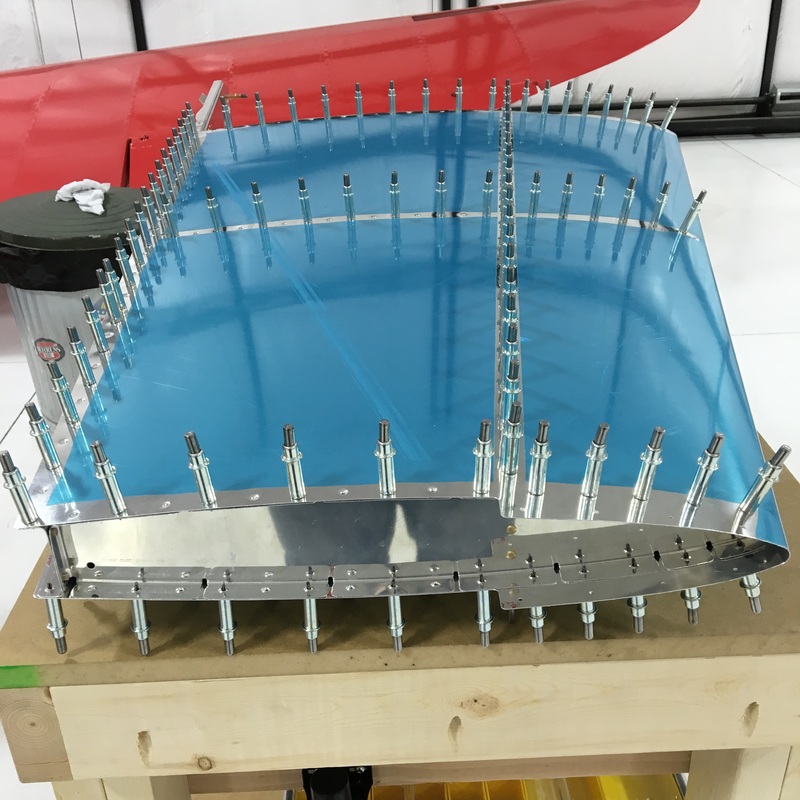
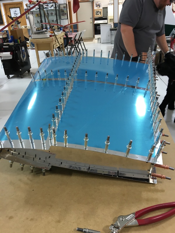
We put in most of our build hours over the weekend, so Friday nights at the hangar are a pretty common occurrence for us. We'll even take the dog with us and make it a family affair. Zoey is finally getting more tolerant of all the loud noises we make (especially while riveting). Last night she found an out of the way place and napped while we worked. 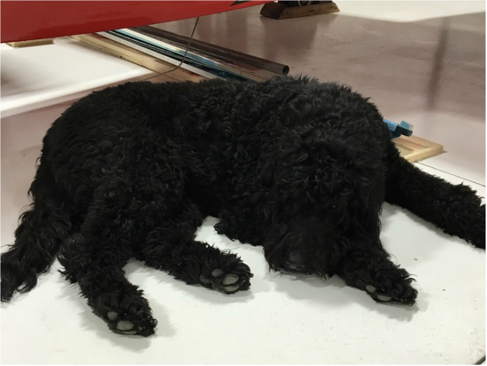 She might have also been annoyed because she was bored. Zoey prefers to be at the hangar when there are a lot of other people working on projects. I think she has these people divided into three categories - people to pet her, people to play with her, and people to feed her popcorn. Friday night was a big transition for us, we finally finished the vertical stabilizer and moved on to the next section of the empennage. Mike has to keep a detailed build log so the FAA will give us our Airworthiness Certification for Amateur-Built Aircraft. The vertical stab took 40 hours to build, and more than 10 of that was spent riveting on the skin - 252 rivets in total (I counted). Now, we have to figure out how and where to store the completed sections of the build so they don't get damaged. The next section of the empennage kit we are going to build is the horizontal stabilizer. 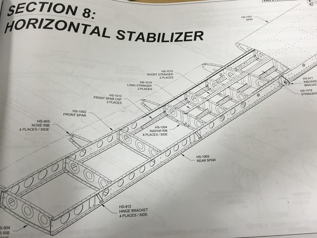 The horizontal stabilizer is the part of the tail that sticks out on the sides. (Here is a nice drawing I borrowed from a website about RC planes.) 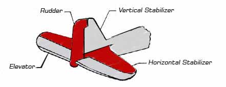 The horizontal stabilizer on our plane is 12 feet long, so we had to clear up some extra space and clamp our two workbenches together. We started prepping and deburring the first few pieces of the horizontal stab. First, we removed the protective vinyl coating from the pieces (all that blue plastic in the left hand photo) and peeled the labels off the smaller pieces. The labels that Vans uses are horrible to remove and almost always leave a layer of glue on the pieces, which we used WD-40 to remove. We learned a few things from our prep work on the vertical stab and ordered a few more tools to make to make the deburring process easier. (Pro tip - If you ever decide to build an airplane, get used to the phrase "more tools.") Mike bought a bench grinder so he could use a fancy deburring wheel. The wheel is made of a really dense material that looks like cement but feels more like wood. It made quick work of deburring the thick reinforcing parts. The wheel wears away over time and has to be replaced (hopefully not often because those wheels are expensive!). While Mike was using the power tools I worked on deburring the edges of the really long piece using hand tools. Every single edge has to be smoothed using a combination of deburring tools and files. If done correctly, you should be able to run your finger along the edges without feeling any rough spots or metal chips. These pieces are much bigger than anything we worked with on the vertical stab and we created a lot of metal shavings from those two pieces (Mike likes to call it glitter). Next up, drilling some holes and countersinking.
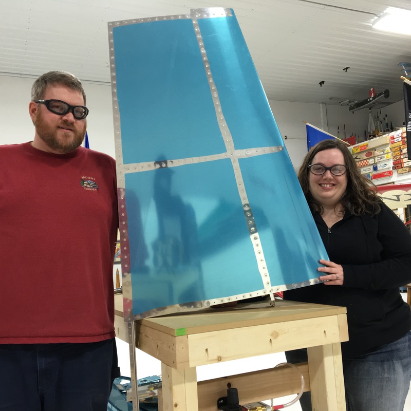
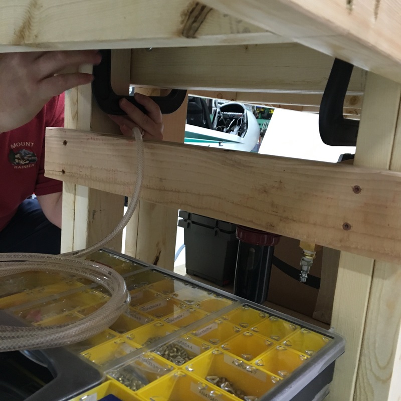
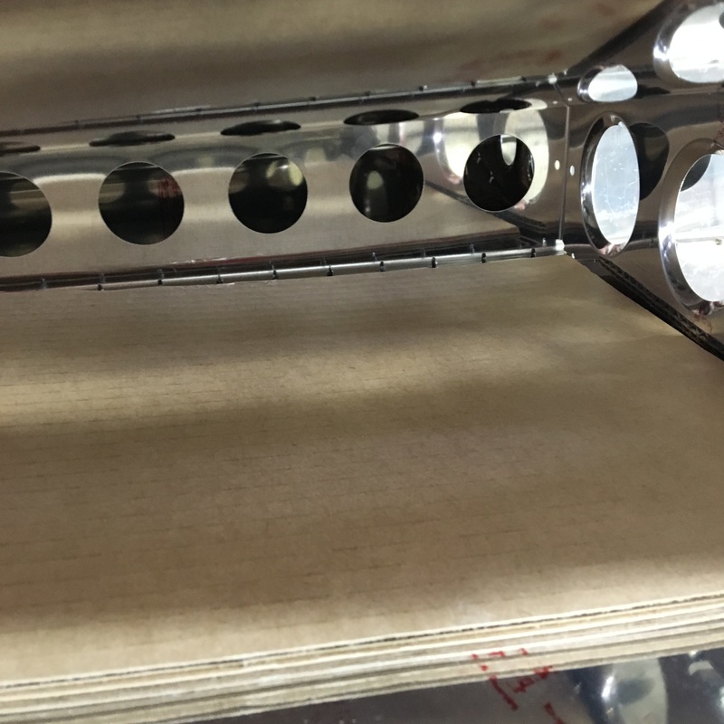
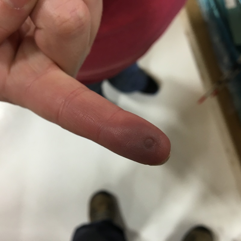
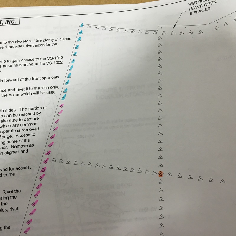
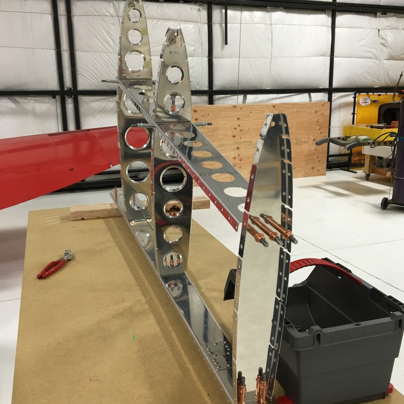
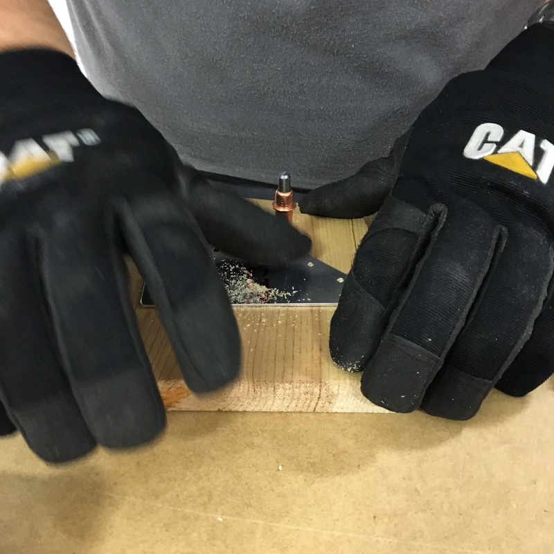
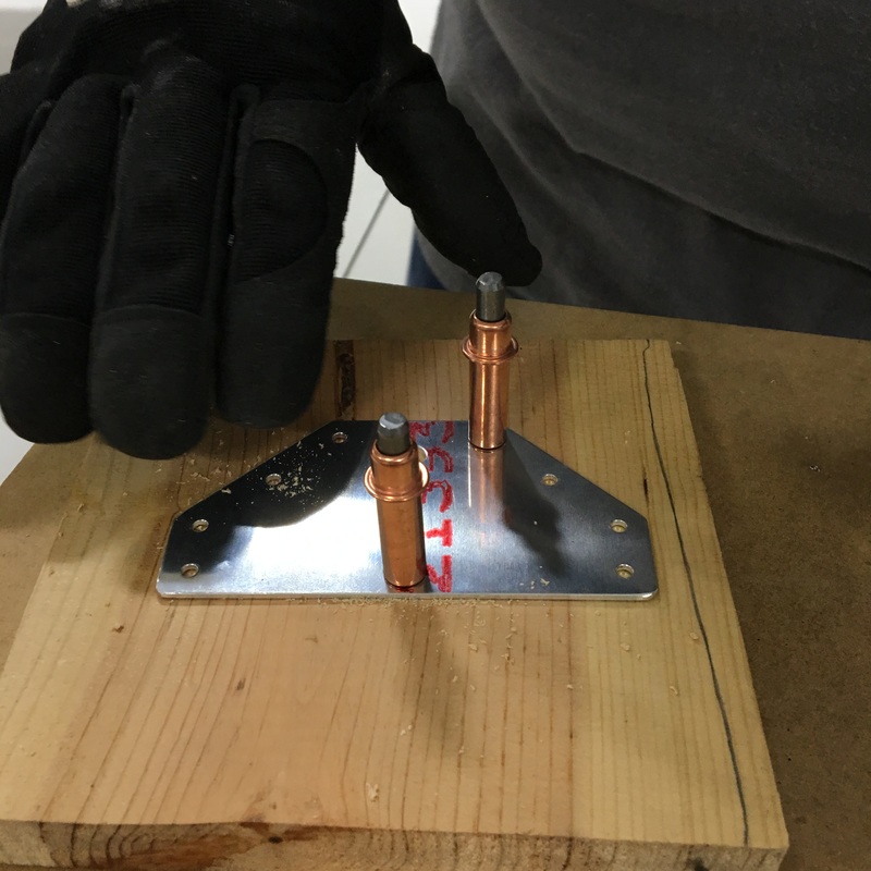
I can't believe that it's been a month since my last post! To put it simply, progress has been slow lately. We've had several issues that have slowed down or delayed progress - I spent a week in New York for work, the air compressor at the hangar broke, and Mike had an appendectomy (while I was in New York for work, that was fun). Mike's recovered very quickly from his surgery, but can't lift more than 15 pounds right now. That's meant that I've gotten to do some of more physical tasks while we (finally) finished the vertical stabilizer. Last time you tuned in, Mike and I were making good progress on riveting the skin onto the vertical stabilizer. I've got to say (now that we're 99% finished) that there are a LOT more rivets than I realized. I would have estimated that we were half way done at the end of my last post but I think a more realistic estimate would have been a third done. The riveting felt like it would never end! It didn't help that there were a few sections that were really difficult to access and subsequently exhausting to work on. The most challenging section to rivet was along the spar that runs down the middle of the vertical stab. If you look at the picture below, I'm talking about the row of clecos that runs vertically down the center of the picture. 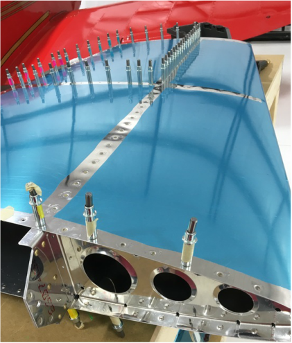 To get to these rivets, you have to remove as few rivets as possible and squeeze your arm under the skin. 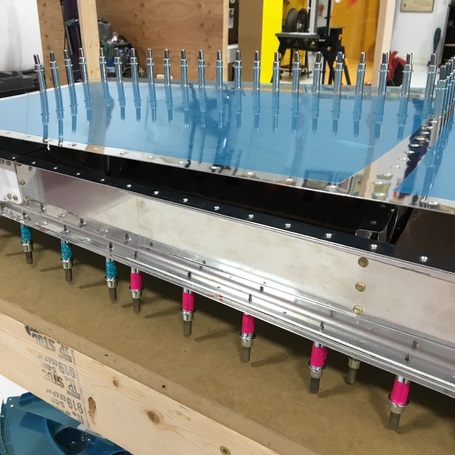 Guess who got to do that job? 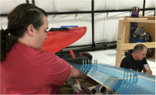 It's a really awkward position and I could only buck a few rivets before I had to take a break. As Mike ran the rivet gun on the outside of the skin, I would try to brace the bucking bar against a rivet that I couldn't see. Mike also warned me not to drop the bucking bar because I would dent the skin (apparently this is a pretty common occurrence and there are lots of cautionary tales online). To help protect the skin just in case I dropped something, we put a piece of cardboard inside. It was also very hard to see the rivets to check and make sure the shop head was the right size and using our rivet gauge was pretty much impossible. So, we used the handy finger indentation method. I would hold my finger on the shop head for a few seconds and then we would compare the indent left in my skin to the gauge. I was so relieved to be done with this section! This was definitely one of the more physically uncomfortable parts of the build so far and I will admit that I was pretty whiny that day. From there, we finished riveting the inspar rib (which runs horizontally across the vertical stab), which again involved sticking my entire arm inside of the airplane. 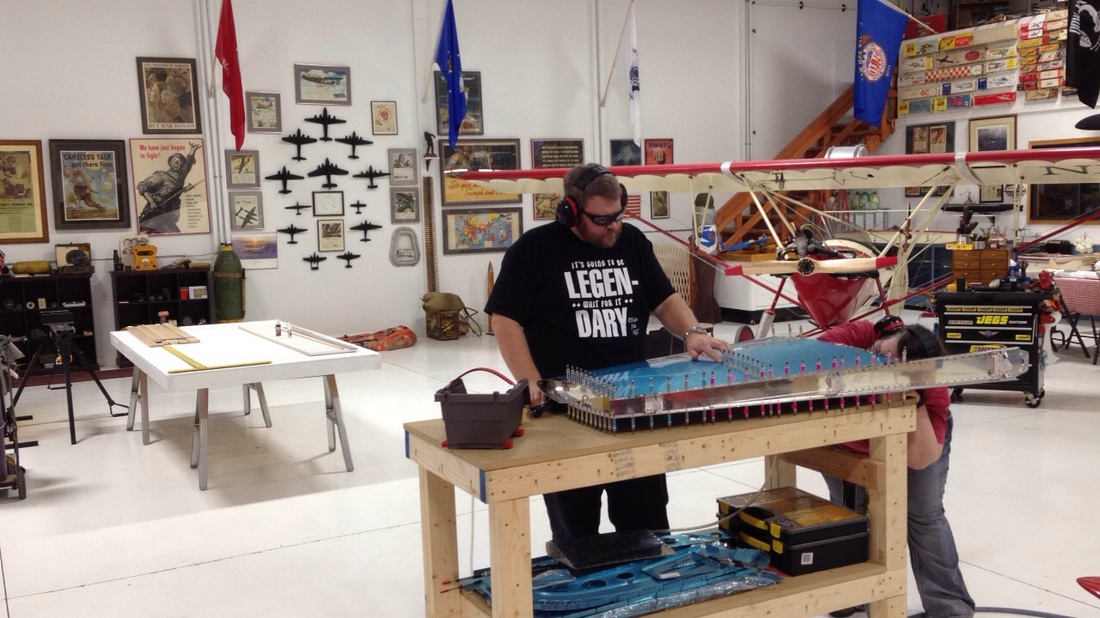 Finally, we only had the edges to rivet. They were a piece of cake considering we could see them and access them easily. This was about the time that the air compressor broke. We could have finished the edges using the manual rivet squeezer (which we actually did for one section) but there were a few really big rivets where were really needed the rivet gun (and hence the air compressor). I don't really remember what these big rivets were for - probably holding some rib to some spar (which is about the most generic airplane sentence I could possibly write, everything seems to be called either a spar or a rib). I took a picture comparing these big rivets to what we had been using on the skin (the rivet on right). I grabbed a razor blade out of our tool kit to provide some scale. 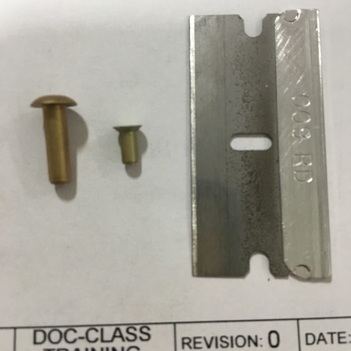 The last bit of riveting also required some creative problem solving so we didn't damage the skin. As I've said before, nothing on the airplane is square or flat. Up to this point we had been able to put a piece of 2x4 under one side of the vertical stab to keep everything stable while we riveted. This didn't work very well on the rivets along the bottom edge and at one point the whole piece slipped while we were riveting. Not only was that kind of alarming, it's also not very good for rivets... 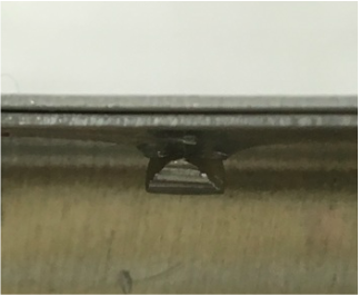 At this point we were kind of desperate to finish, so we improvised a more stable base using couch cushions. 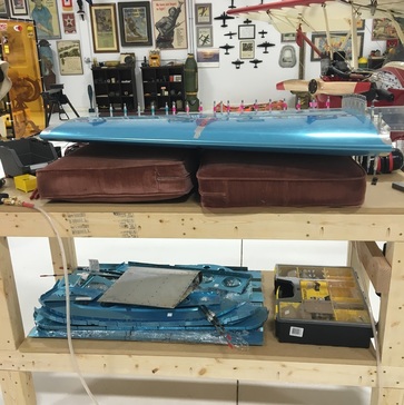 We plan on getting some sheets of foam to use in the future, but the couch cushions worked surprisingly well. The last step was to finish the rivets along the back edge. We opted for the manual rivet squeezer because there were a lot of people at the hangar that night and the air compressor and rivet gun can get pretty noisy. The rivet squeezer also has the advantage that once you get the depth set, you don't have to check every single rivet to make sure it's properly driven. The rivet squeezer takes quite a bit of strength and Mike's weight lifting restrictions are still in place so I got to be the muscle for this section. 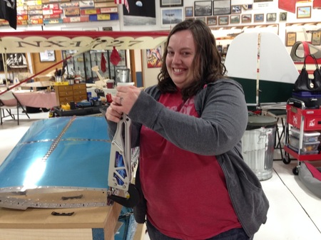 I wish I could say that we were completely done with the vertical stab, but we still have 6 rivets that we couldn't get to with the squeezer. We'll have to fire up the rivet gun to finish those off. I think that our final product looks pretty good! 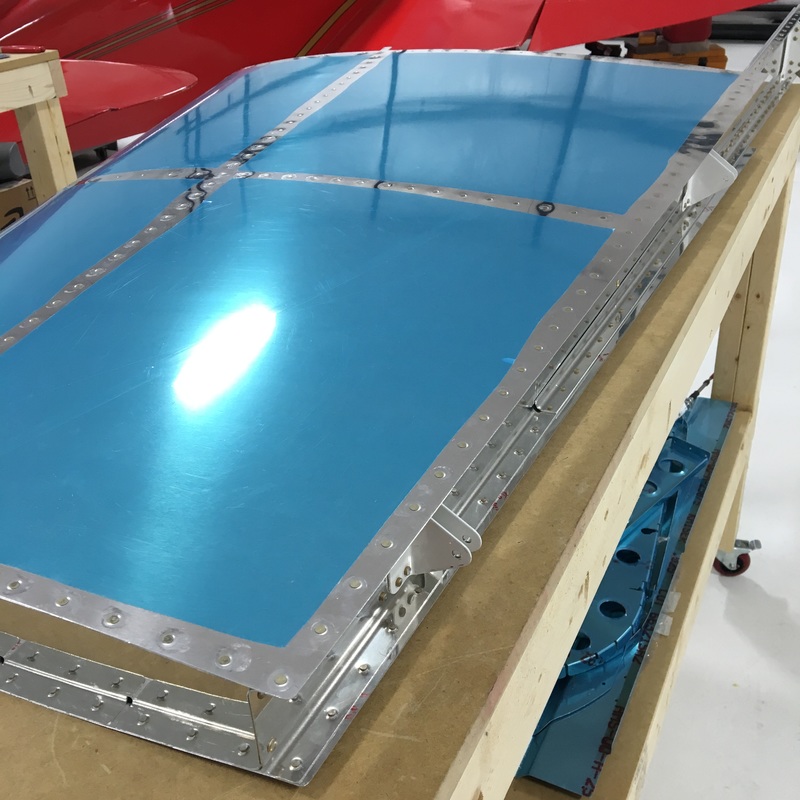 You may remember that we've had some trouble in the past with accidentally using the wrong size of rivet. That's because the directions for riveting look like this: 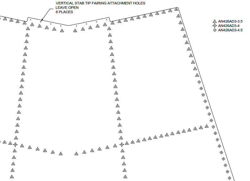 Be careful not to misread one of the symbols in the drawing, or one of the numbers in the rivet description, or miscount how many triangles there are before they turn into diamonds. I had an idea of how we could avoid a repeat of our last adventure with replacing rivets and it involved crafting supplies. Now, I'm not really a crafty kind of gal, but I have seen enough Pinterest posts shared on Facebook to know about washi tape. My bright idea was to buy matching sets of highlighters and washi tape and use that to keep us on track. We assigned a color to each shape on the drawing and then marked the corresponding cleco with the matching color of tape. It worked surprisingly well and made for some very colorful airplane pictures. Quite honestly we could have used a lot less tape and just color coded the first and last cleco for each size of rivet. But...I liked the way it looked and went a little crazy (maybe I'm a little more crafty than I want to admit). So, here are some gratuitous photos of taped clecos. In my last post, I mentioned that the instructions for this part of the build are very, very important. Here's why...the vertical stab is essentially a long, box and all six sides of that box are sealed. But wait, you may say, what about that row of clecos that runs down the center of the skin. How can you possibly put a rivet in those holes if all sides of the box are sealed? Hence, the importance of carefully following the instructions. At some point, some really experienced builder figured out exactly how to reach every single rivet hole and put all of that information in the instructions. Here's a sample: 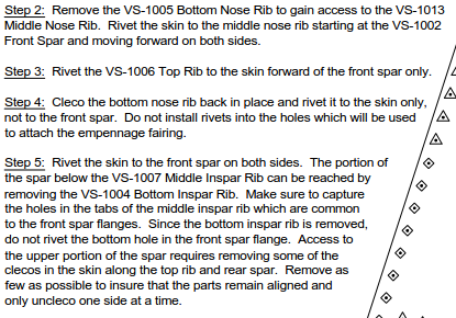 Clear as mud, right? Basically, you remove certain strategic pieces of the skeleton so you can reach different sections that you need to rivet. The rivet gun is the only way you can install these rivets because there's just absolutely no way to could get a rivet squeezer big enough to reach these middle rivets. (OK, I hope Mike doesn't read that last sentence because there probably is some sort of (really expensive) rivet squeezer that could do that job but I just really don't want to buy any more tools right now.) The first thing we got to do was out a piece (the bottom nose rib) so I could reach inside with the bucking bar. 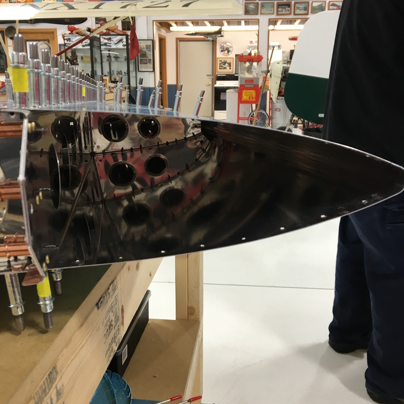 I didn't measure the distance from the edge of the vertical stabilizer to those center rivets but I can tell you that my entire arm, all the way up to the shoulder, was inside that thing. I definitely had the harder job in this case because not only was I trying to fit my entire arm inside of that narrow hole, but I was also holding a heavy bucking bar in my hand. It is also really hard to get the bucking bar in the right place when you can't see what you're doing. We had a few missteps, but here are the first rivets that will actually be visible on the outside of the plane. 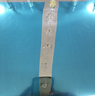 If you look closely, you'll see a divot around the second rivet from the top. That's where I thought I had my bucking bar in the right place, but was wrong. I also now realize why Rosie the Riveter was so buff, this is a great arm workout. Two hours later, we are about half way done. We still have to do the area in the upper left hand corner where you see all the clecos. That should be really interesting because the only way to access the center rivets in that section is to remove as few clecos as possible and stick your hand under the edge of the skin. Doesn't that sound like fun? 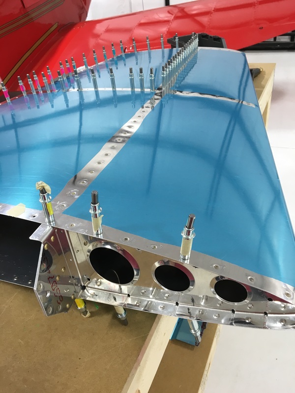 Now that we've fixed the problem started by that rogue drill bit, we can finally begin final assembly of the vertical stabilizer. I honestly can't even remember how long we've been working on this one piece of the plane. Has it been two months, three? OK, so I just looked back at my earlier posts and it's only been about six weeks. It just feels like a lifetime. This is the part of building that gets really exciting because you can finally see a finished product. It's also the part of the process where the instruction manual becomes very, very important. I'll talk about that in my next post. For the very last time, we assembled all of the pieces that we've been working on to create the skeleton of the vertical stabilizer. First, we used clecos to hold everything together, then we put in the final rivets. Amazingly, the whole skeleton is only held together with 11 rivets. Even riveted together the vertical stab felt really flimsy at this point. Mike assures me that most of the strength and stability comes from the skin being riveted onto the skeleton. Everything on the skeleton is curved so we had a few challenges installing some of the rivets. To make everything even harder, there were a few clecos that stuck out at odd angles but couldn't be removed. We finally figured out that if we clamped some boards to the end of our work bench, we could move those boards around to accommodate whatever structural components or clecos were in the way. We also had our first opportunity to do some offset riveting. An offset rivet set has a curve so you can work in tight areas or around structural components. It was kind of weird to use but we tried it out on some practice pieces first and everything went just fine. 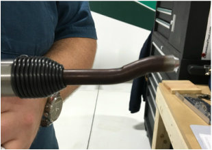 Once the skeleton was riveted together, we put the skin on over the frame. Two hundred clecos later, it looked like this. 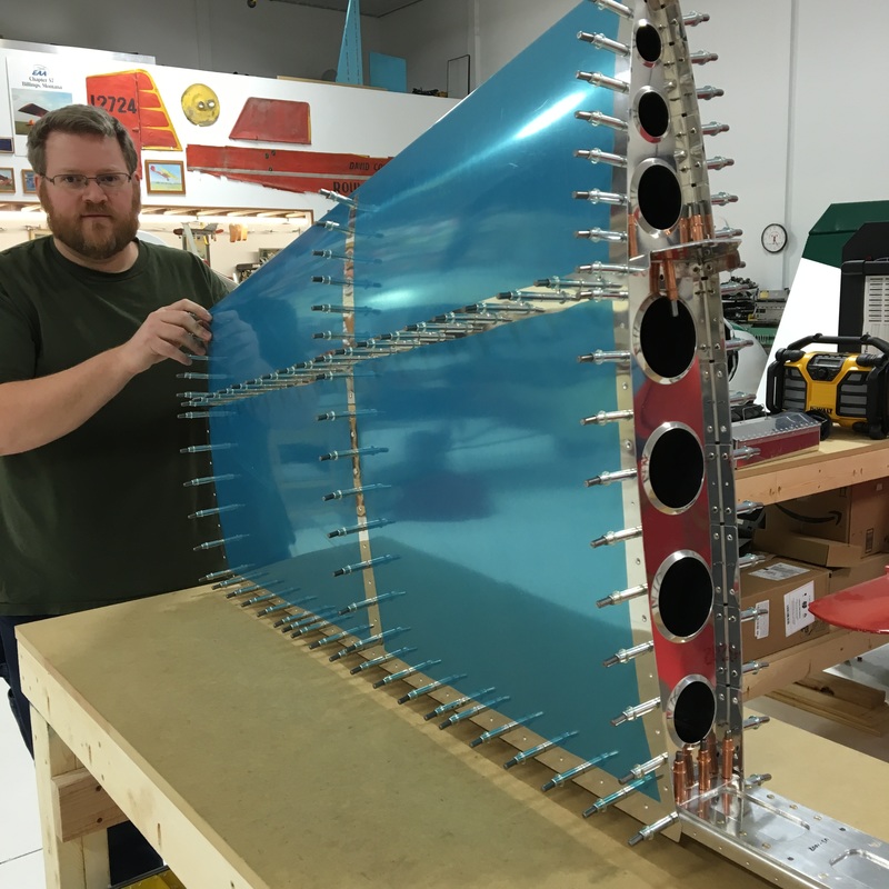 Now just for fun, here are two pictures of the vertical stabilizer. One of these pictures is from the first time we put the vertical stab together on January 16. The other picture was taken last Saturday, February 18. Can you tell which is which, because I sure can't? One month of work and we're right back where we started. I've realized that I completely misunderstood the amount of energy required to build a plane. I don't mean that building a plane is physically hard, because honestly it's not. At this point, at least, the parts are small and nothing is particularly heavy. The thing I got wrong was that I underestimated the amount of mental energy it would require. I've referred to it before, but building is really just one long exercise in problem solving. Mike knows A LOT more about building a plane than I do - he's been reading about kit planes and anticipating this project for more than 10 years - but this is still his first build. You've read everything that I know about building airplanes because I've written it all down here. We are both in new territory and spend a lot of time questioning if what we are doing is correct or good enough. Add to that uncertainty our recent stretch of, not so much bad luck, as things just not going quite right and I think we're both a little mentally worn out at this point. For every thing I've written about in the past, there are probably 2 or 3 other problem solving steps that I could have included. I'm trying to stay positive about the build, so today I thought I'd write a little bit about the types of problems we are encountering and how we solve them. A couple of weeks ago, we encountered two specific problems. First, Mike has trouble drilling the countersinks into a small, thin piece of reinforcing metal. Here's a picture to remind you of what happened. That hole should be perfectly round, which is very obviously is not. We had to order a replacement part and start over. 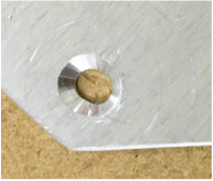 Mike did a little research and found an ingenious way to make sure that the metal stays still while he makes the countersinks. He drilled holes into a scrap of wood and used clecos to hold everything still while he drilled the countersink. Two minutes later, the replacement piece was ready to use. I was surprised that you could use clecos this way. I think I suggested to Mike that when we're done building we could use all of clecos to design some sort of wall mural in our house. I was joking but if you visit us at some point in the future and see a wall full of clecos, you can remind me to keep my mouth shut next time. Yesterday we decided to tackle our big problem from last week - the ugly mess created by the broken drill bit. We spent a lot of time discussing the pros and cons of the two options we had come up with - making the hole bigger and using a universal head rivet two sizes larger or countersinking the hole and using a flush rivet one size larger. We decided to try option 2 to get rid of most of the damage by countersinking That way, if things really don't work we still have the option of using a an even larger size rivet. Creating that countersink was a really nerve wracking process, probably because last time we tried to fix the problem we just made it worse. Mike used a drill press to make sure the countersink was centered properly. We don't actually have any of the size rivets we will be using so he had to use calipers to get the hole the right dimensions. The countersink removed most of the damage and hopefully it will be all right. Once the countersink was done, he enlarged the rivet hole (from the back). We had to order the rivet we needed to finish the repair. Actually we had to order 1/8 of a pound of rivets because that's how they are sold. We had hoped to use a rivet only one size larger, but the countersink was too large so we had to go up two sizes. Below you can see how the first rivet was way too small (left picture) and the properly sized rivet on the right. We also got to try out a new tool that Mike ordered called a chip chaser. It's a really thin piece of metal with a hook on the end that you can use to remove aluminum chips from tight spaces. Honestly, it looks like a tiny "slim jim" that you'd use for unlocking a car door. It was pretty hard to fit even that thin piece of metal in between those two pieces but we pulled out a few tiny pieces of aluminum so I guess it was a good idea. Finally, after several weeks of trouble shooting and ordering tools and rivets, we finally go the problem fixed! 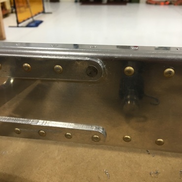 That single rivet has really held things up because we can't move forward with any assembly until that problem was fixed. Our next steps are to reconstruct the vertical stabilizer skeleton and rivet the skin into place.
|
AuthorThe supportive spouse's guide to building an airplane. Archives
May 2017
Categories |


 RSS Feed
