|
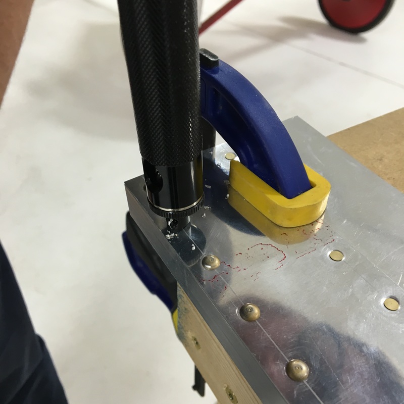
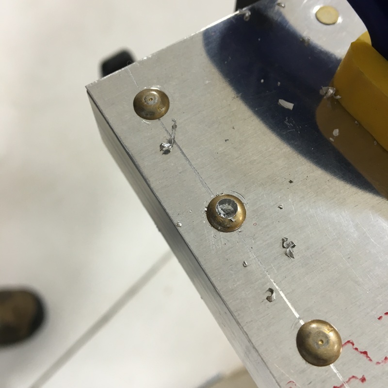
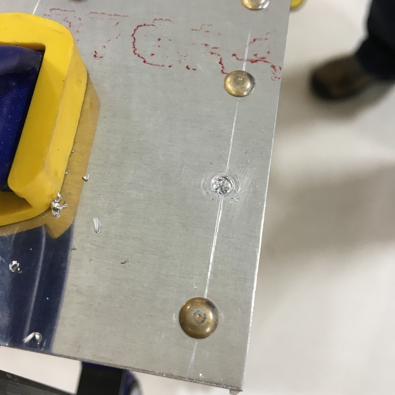
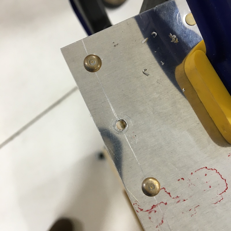
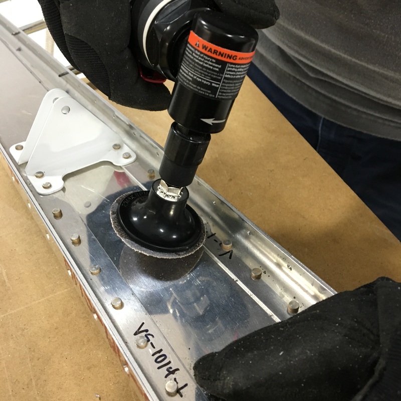
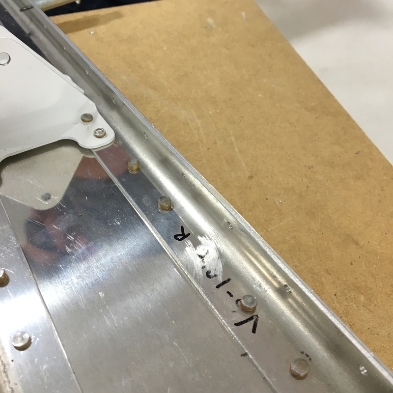
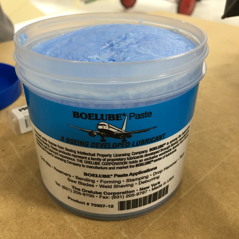
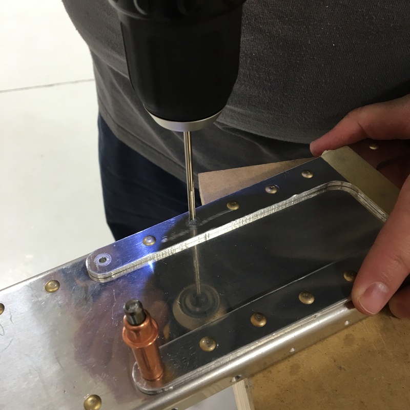
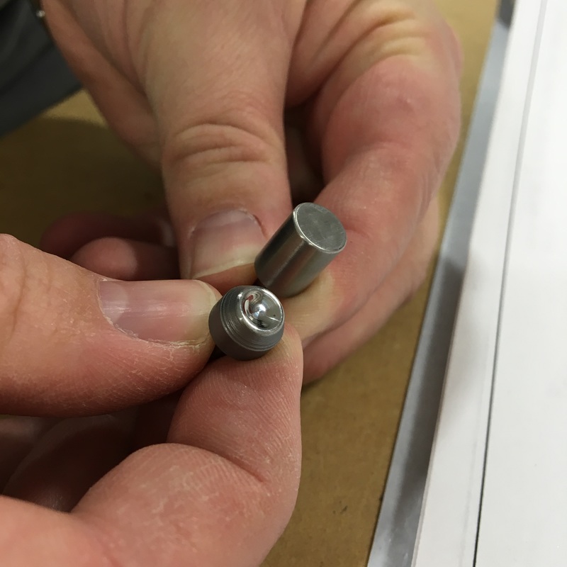
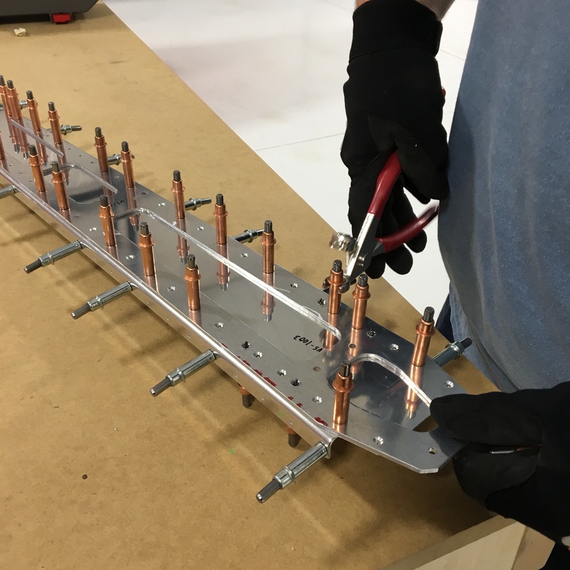
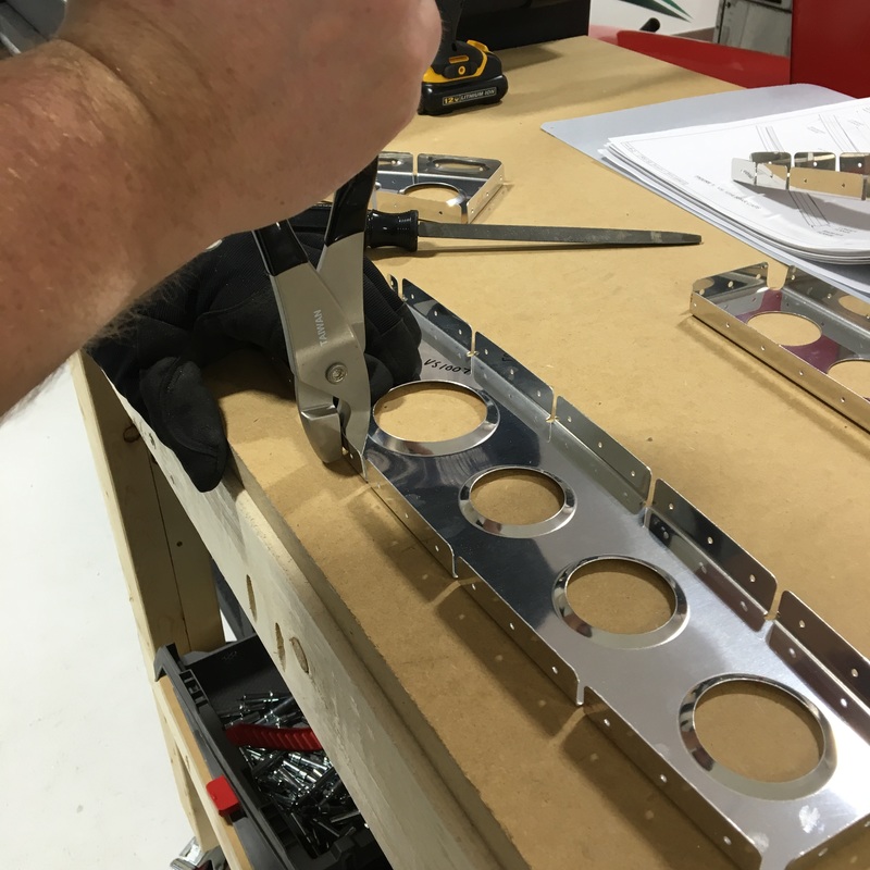
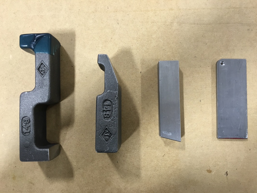
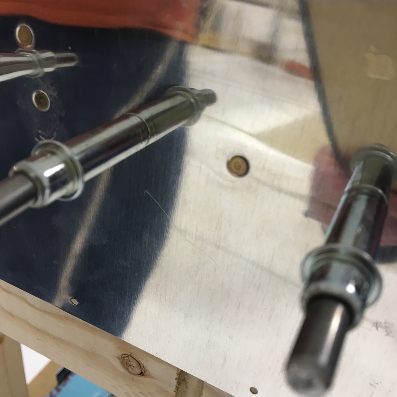
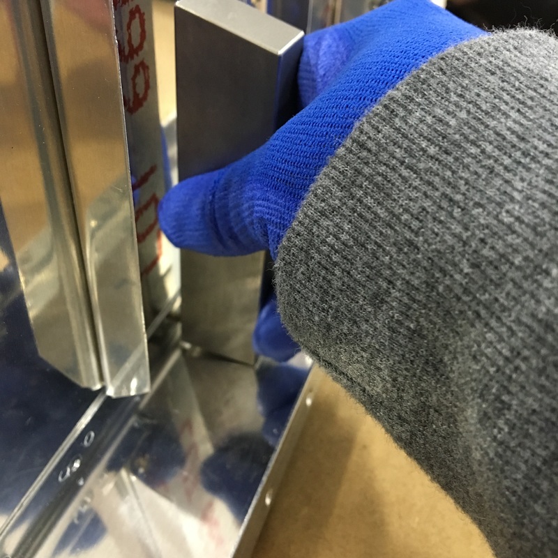
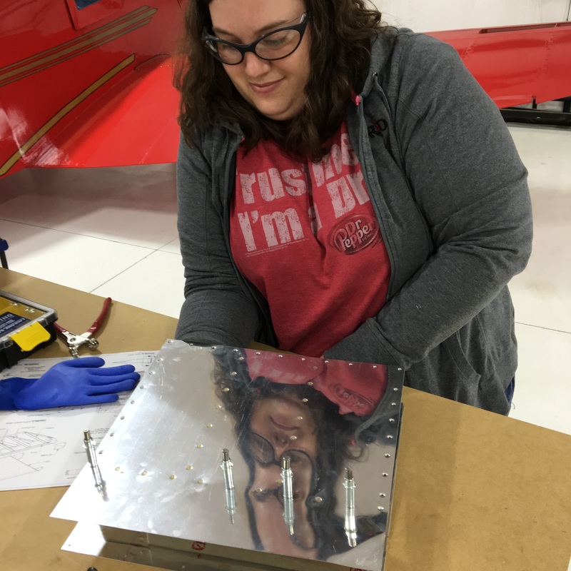
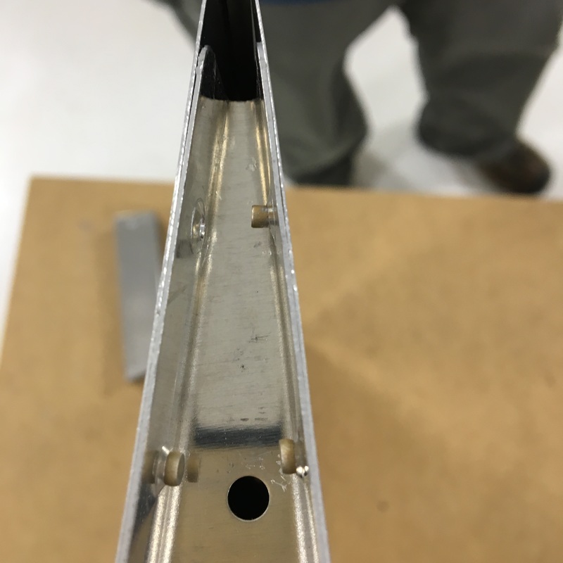
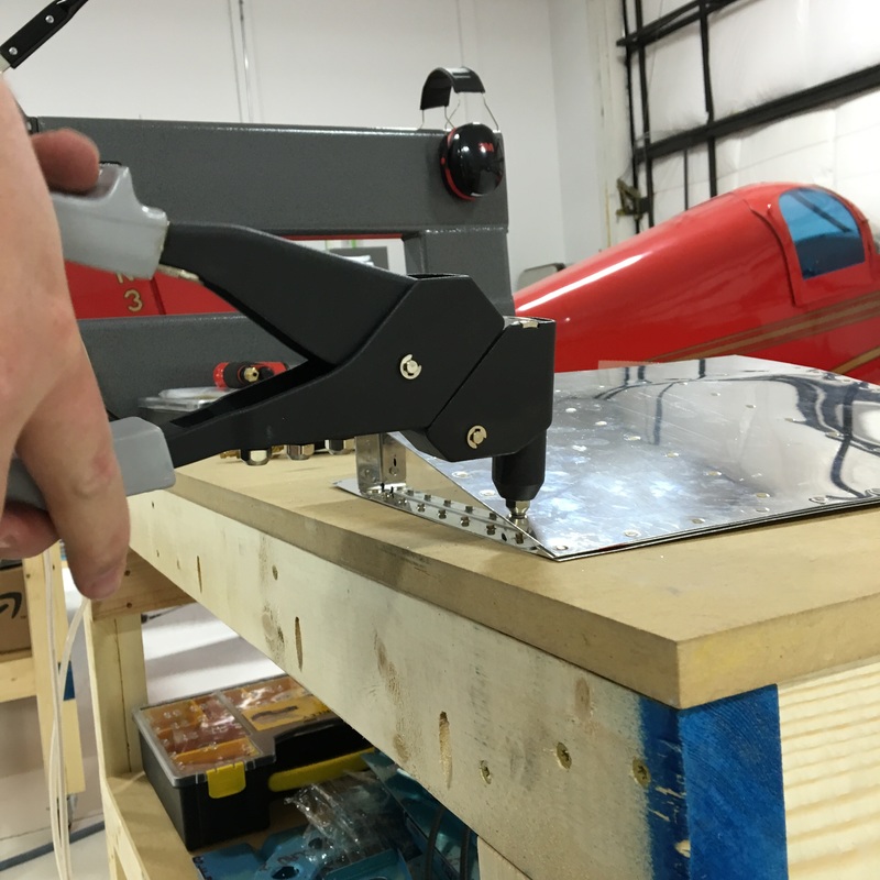
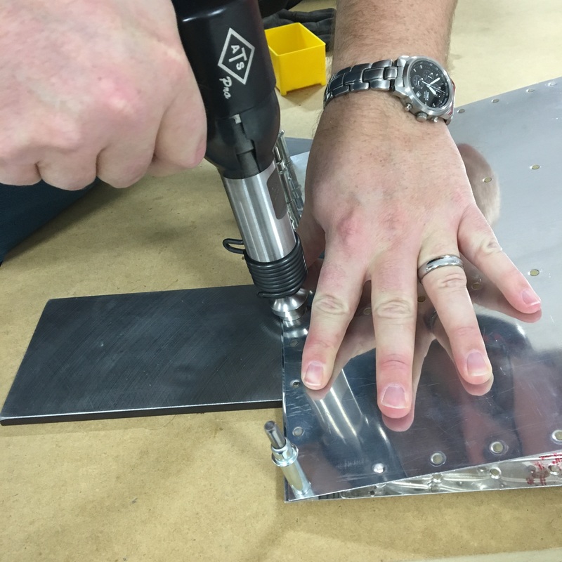
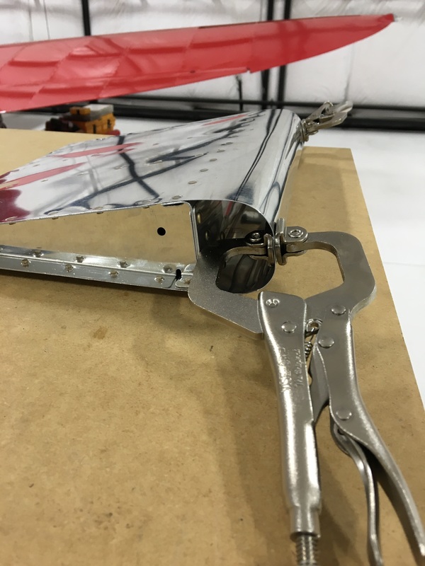
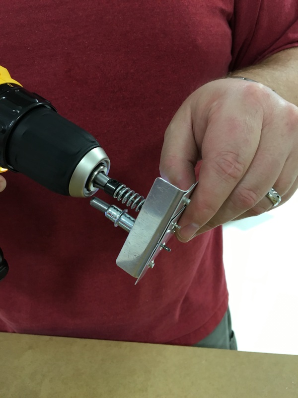
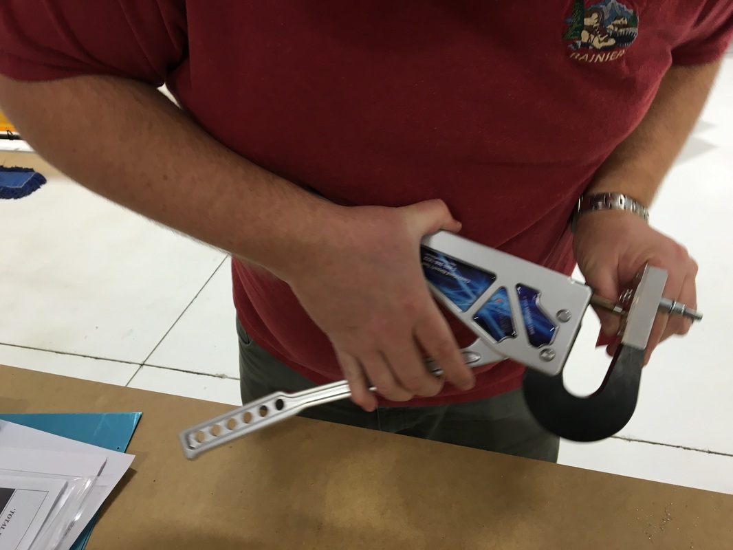
In theory, removing rivets is easy. I believe that last sentence is what they refer to as foreshadowing. It took us two hours to undo our mistakes from last week. Yes, two hours to remove and replace six rivets. Actually, if I'm being honest it took about 45 minutes to remove one rivet and then a little over an hour to replace the other five. We even practiced with the new rivet removal tool first so we wouldn't mess up the actual plane. Unfortunately our practice conditions weren't very realistic for the situation that we were dealing with. The theory of rivet removal goes like this: 1. Remove as much of the rivet head as possible; 2. Punch out the remaining shank of the rivet (that's the straight part of the rivet, it can also be called the shaft); 3. Replace the rivet. We followed that process and it worked pretty well on our practice piece. We even got a special tool that helps with drilling out the head of the rivet (we spent most of this last week waiting for that tool to arrive). You can see that rivet removal tool in the upper left picture below. There is a drill bit inside that big black tube and a guide on then end that fits over the head of the rivet. This is supposed to help you drill exactly in the center of the rivet so you don't accidentally damage the surrounding metal. Once you get the rivet head drilled out (top middle picture) it's easy to snap off the rest of the head (top right pic and bottom left). Finally you use a punch to push what's left of the rivet out of the hole (bottom middle and bottom right pics). It all worked perfectly on our practice piece. When everything goes smoothly, this is what you end up with: 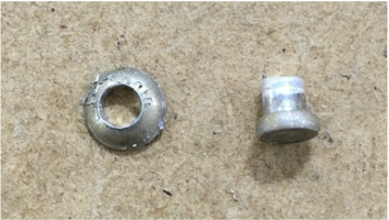 Once we practiced that process a few times, we started work on the actual plane and things didn't go quite so well. Our first problem was that the rivets on the plane were quite a bit larger than the rivets on the practice piece. Mike was able to drill and remove the head of the rivet just fine, but the shank seemed like it was welded in place. Mike tried and tried to hammer the shank out of the hole but we didn't have any luck. We figured that we hadn't drilled deep enough when removing the head so Mike tried to use the drill to remove a little more of the rivet. That's when we encountered problem number two and things started going really wrong. The second problem was that the drill bit that came with the rivet removal tool was a piece not very high quality (a.k.a. a piece of junk) and broke almost immediately. I guess the third problem is that we didn't notice the broken drill bit because it was hidden by the outside casing of the rivet removal tool. I didn't get a picture of the broken drill bit, but the end of was totally mangled. When Mike tried to drill out a little more of the rivet the bit started to shimmy all over the place and we ended up with a pretty ugly mess. 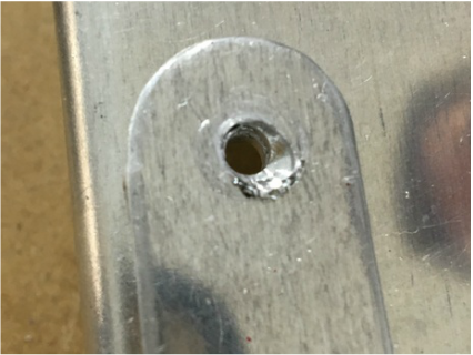 Building an airplane seems to be largely a process of solving one problem after another. In the picture above, you are seeing the final product - after we spent another 20 minutes to get the rest of the rivet out. That was quite a process and involved lots of discussion and weighing of pros and cons. I doubt our final solution was win the approval of an experienced builder but we managed to make it work. We decided that it would be best if we removed the shop head of the rivet and drilled it out from the other side. We did that using an angle grinder. Then Mike very carefully drilled of the remaining rivet shank using a drill bit that wasn't broken. Once we discovered the rogue drill bit and replaced it, the rest of the rivets came out pretty smoothly. When we started replacing the rivets we had a couple of places where it seemed like the holes had shrunk and the rivet wouldn't fit. 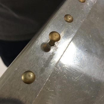 Help, I'm stuck! It's a pretty common problem when you are replacing rivets. Some tiny little piece of metal gets stuck in the hole and binds everything up. Mike used a special drill bit, called a reamer, to clear any debris from the hole. The reamer is designed so it won't enlarge the hole the way a regular drill bit might. The best part is that when you use a reamer you get to use this stuff called BoeLube Paste. We got the rest of the rivets replaced pretty quickly after this. We're still trying to figure out how to deal with problem we created thanks to the faulty drill bit. We are considering two possible solutions right now - make the hole big enough to get rid of the problem or use a countersink rivet here instead. Neither is a great solution and we are weighing our options. New Vocab:
Shaft/Shank - the straight "pin" on a rivet Reamer - a special drill bit used to remove debris from a rivet hole (it probably has more uses but I don't know what they are yet)
0 Comments
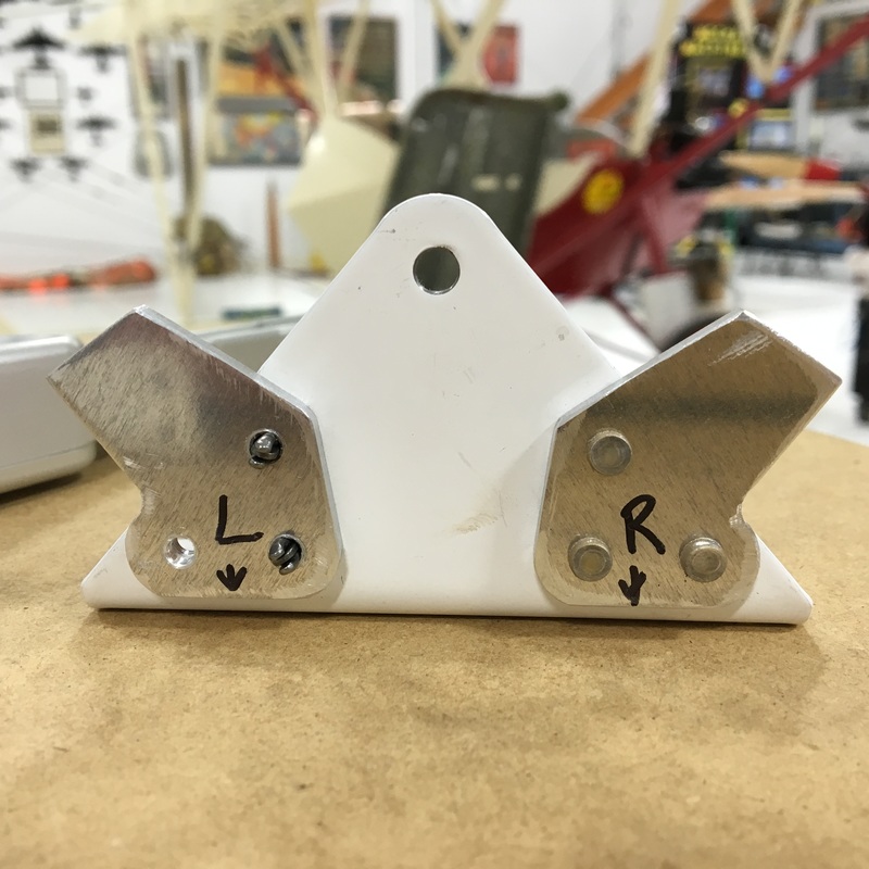
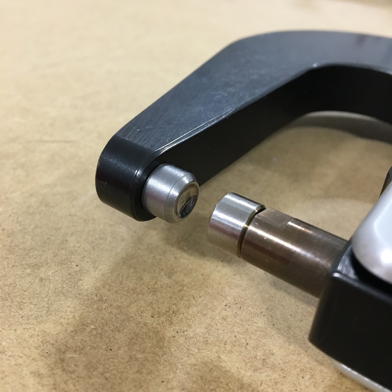
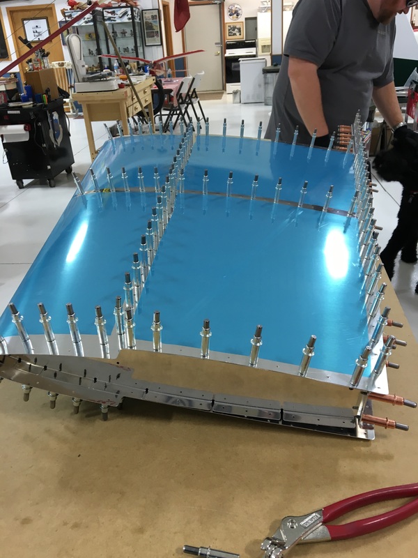
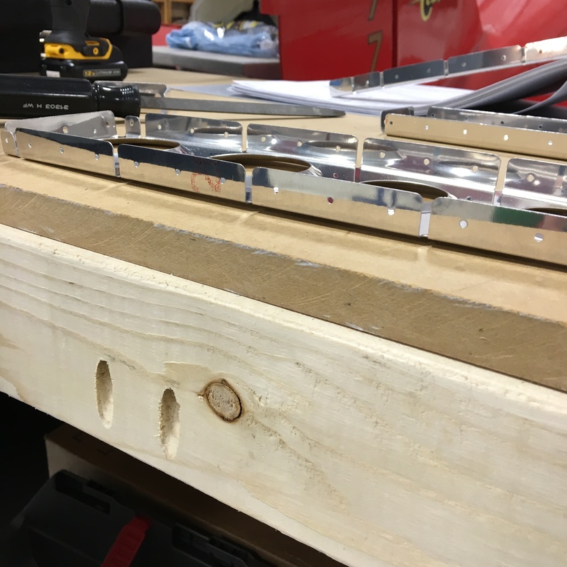
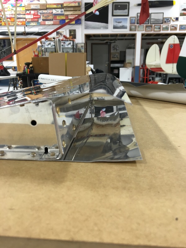
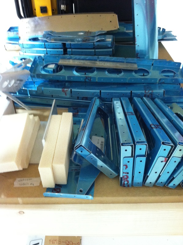
It seems like I say this every time I start writing, but it's been a big week for us. There are just so many milestones as we really start building the plane. Every time we work it seems like we are doing something for the first time. This week we set our first rivets and made our first mistakes. We'll get to the mistakes, but let's start with the rivets. Those three rivets may not look like much, but they represent a big first for us. Now that those rivets are in place, we will never have to take those pieces apart again. Once we repeat that process about a million more times we will have an airplane. I'm not quite sure what this part is, I think it's a bracket that will eventually connect the vertical stabilizer and the rudder. You may notice that the rivets we used are different than what I've talked about in the past. There are two different types of rivets - flush rivets which is what I've talked about before and universal rivets, which is what you see above. Here's a practice kit Mike worked on that shows both kinds - flush rivets on the left and universal on the right. The vertical stab uses both kind of rivets. I'm not quite sure when and why each different type of rivet is used. 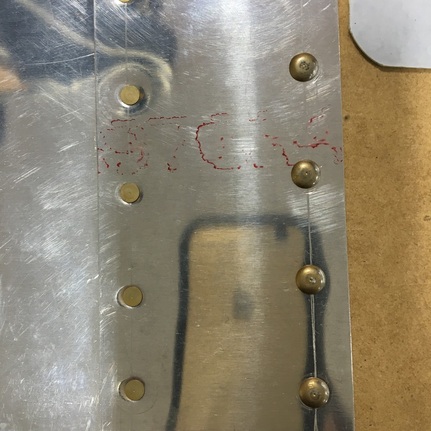 We used the squeeze riveter almost exclusively while putting together the vertical spar. The piece isn't all that big, so all the rivets can be reached with the squeezer. It's also much quieter because we don't have to run the air compressor. The hangar is a shared workspace and when other people are up there we try to keep noise to a minimum. When using universal rivets, you use a die with a little divot that fits right over the domed rivet head. When you squeeze the handles together it squishes the rivet in the right shape. I really enjoy using the squeezer because you can watch the rivet as it changes shape. There's even a little wisp of smoke (or something?) that comes from the rivet as it gets squished. Riveting is one of those tasks that we've found is MUCH easier with two people. Mike will run the squeezer while I hold the piece steady and make sure everything is lined up. Honestly, with the size rivet we are currently using, I'm just not strong enough to squeeze the rivets anyway. It takes a lot of strength and even Mike gets tired out after awhile. There's a lot to pay attention to while squeezing rivets. The cupped die has to sit just right on the domed head of the rivet. The head of the rivet needs to sit flat against the metal surface of the piece. The rivet needs to be perpendicular to the hole so the shop head is an even thickness and isn't angled. It's very easy for things to move out of alignment once Mike starts to squeeze the handles together. We had really good luck with our first several rivets and then we made our first mistake. In the picture to the right, you can see that the rivet isn't sitting flat against the metal. This happened because things just weren't quite aligned and that gap was there when we started squeeze the rivet. The problem is that as you squeeze the two ends of the rivet together to form the shop head, the rivet also squishes outward. Imagine an Oreo cookie - if you squish the two cookies together, the filling in the middle compresses but it also starts to squish out from in between the cookies. Even though we had only applied a little bit of pressure, this rivet was already too fat and wouldn't budge. Once there's a problem with a rivet, the only way to fix it is to completely remove the rivet and start over. We knew this was going to happen (many, many times) during the build so it's not a big deal. Actually, right before this happened I asked Mike if we had the right tools to remove a rivet if necessary. The most amazing thing about the whole situation is that we don't actually have the right tool. I would had sworn that Mike has bought every airplane building tool known to man. So, with my blessing, he gets to order another tool. Now that I think about it, maybe he orchestrated the whole thing so he had a reason to get more tools... As we were inspecting and discussing our bad rivet, we realized that we had actually been using the wrong size rivets and we were going to need to remove and replace several of them. The construction manual describes exactly which size rivet should be used in every single hole. The particular size of rivet is (presumably) chosen for a good reason, and since the rivets we were using were shorter than they should have been we decided that they needed to come out. You can see our mistakes in the picture below. The rivet that wasn't set properly is the one on the right labeled "bad replace". The rivets covered in tape and marked with an "X" are all the wrong size. We had put several other (correctly sized) rivets into this piece by the time I took the picture - they would be the ones not covered in tape. If you're curious, the clecos with tape on the top are marking holes that won't get rivets at this stage. 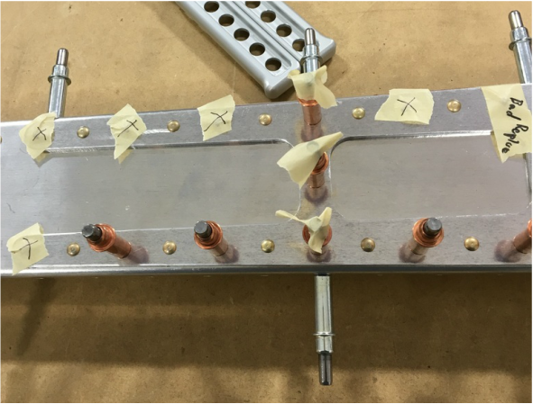 This really isn't a very surprising mistake if you consider the drawings we are trying to follow and the way that rivets are named. Here is a picture of the diagram we were trying to follow. The picture below is about twice the size of the actual printed version and only shows about a third of the diagram. 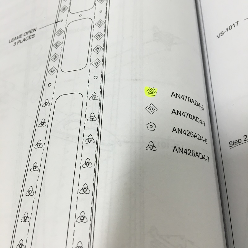 Each shape on the diagram corresponds to a different size of rivet, which is designated in the key on the right side of the page. All those numbers and letters in the "name" of the rivet mean something. The numbers in the middle tell you if it's a universal or flush rivet. The numbers at the end tell you the diameter of the rivet and the length. So in this case we probably should have been using the rivets that correspond to the diamond and accidentally grabbed the rivets that correspond to the triangle. I'm the one that grabbed the wrong size rivets so I've become a little paranoid and have been double and triple checking the diagrams ever since. It honestly isn't a big deal and we just laughed about it but it did make me realize how easy it is to misread these diagrams. Once we get the right tool we will remove those rivets and replace them with the correct size. Mike also had trouble with one other part this week and we got to order our first replacement piece. He was trying to countersink a small, thin piece of metal that provides reinforcement to another part of the vertical stabilizer. The size of the part made this process pretty difficult and the holes weren't round anymore when he was done. It's kind of hard to see in the picture below, but on the left side you can see that the hole is oblong rather than round. When Mike did some research online he found this is a pretty common problem with this particular part. We'll order a replacement (which thankfully only costs a couple of dollars) and try again. 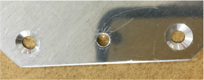 So, progress is stalled for a few days while we wait for the rivet removal tool and the replacement part. This time gives us a chance to figure out how to avoid these mistakes in the future. New Vocabulary:
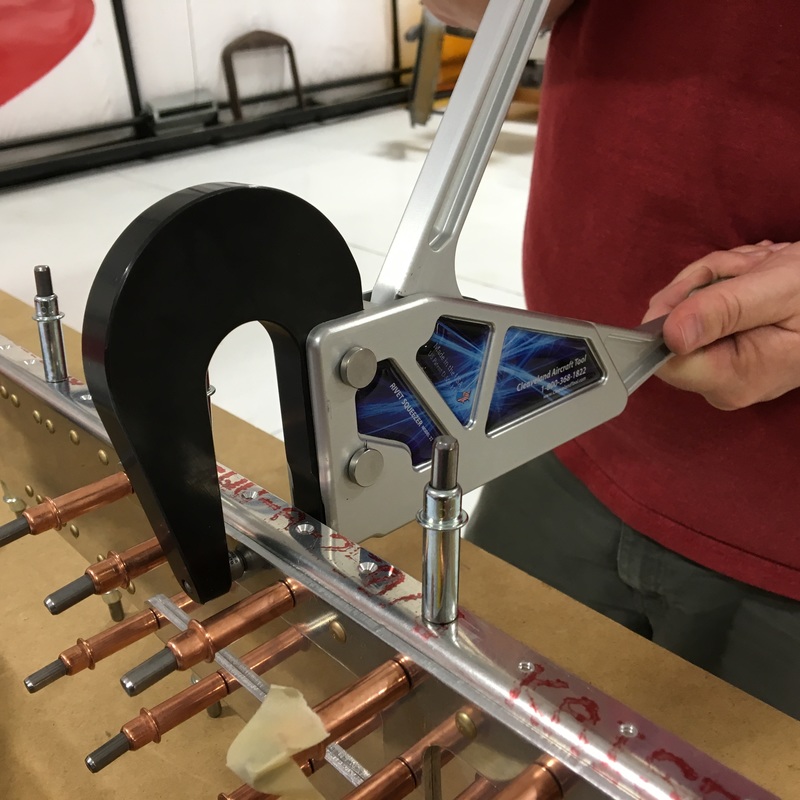
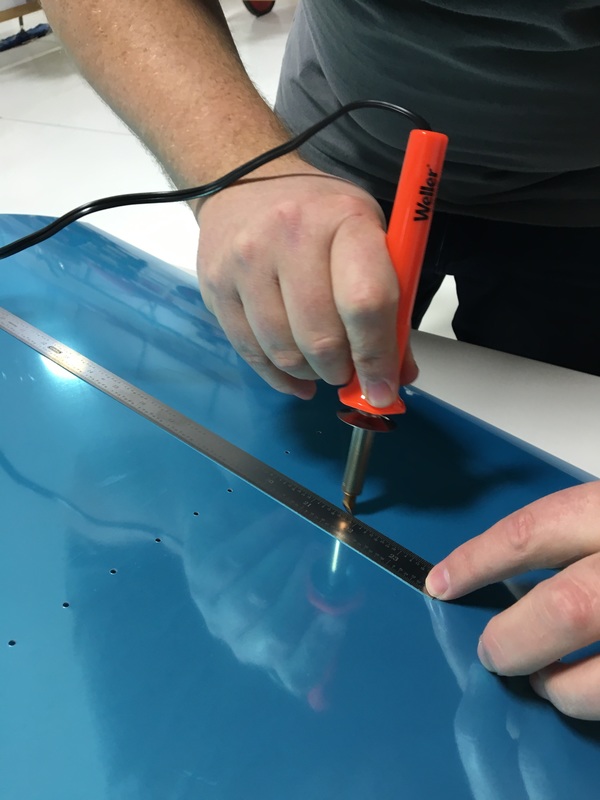
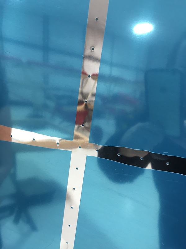
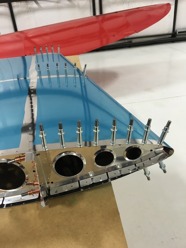
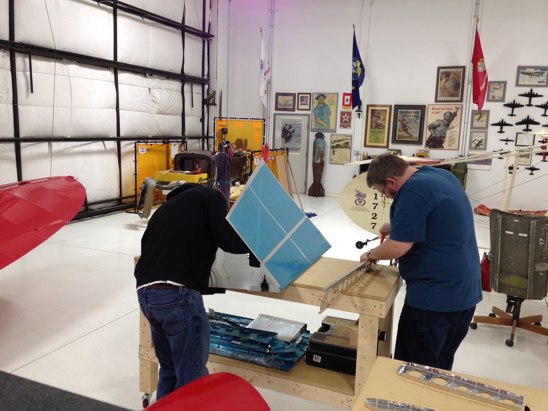
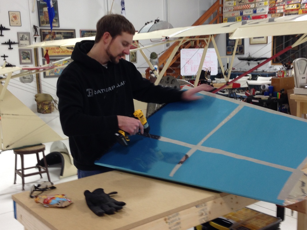
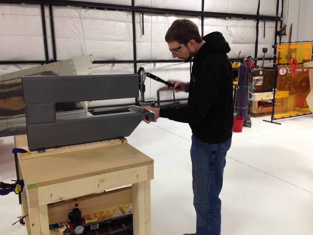
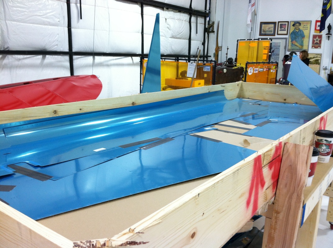
Universal rivet - a rivet with a round, domed head Die - a tool that is used for cutting, shaping, or stamping a material or an object (definition from the Merriam Webster online dictionary) I've learned a big lesson about building airplane this week - sometimes it's hard to see that you're making progress. We've been continuing to work on the vertical stabilizer and since my last post we've put the whole thing together...and taken it all apart again. Apparently, putting things together and then taking them apart so you can put them together again is a big part of the build process. Now, I have to be honest and say that Mike did warn me about this. I believe he said that we will basically build our airplane four times before we are done. It can be a little disheartening to put in several hours of work to end up with the same pile of pieces you started with days ago. But, I suppose it's all progress and every single step gets us closer to a finished product. You might remember that at the end of my last post, we had finished putting together the guts of the vertical stab. I don't think that "guts" is an approved airplane term but I have no idea what else to call it. (OK, I just looked at the build manual and the correct term is actually skeleton.) Here's a little reminder about where we will be starting this week's adventure. 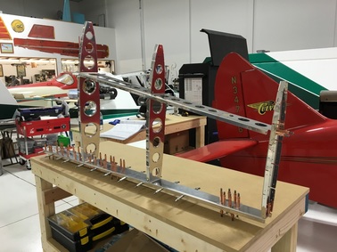 The skeleton of the vertical stabilizer. Our next step was to fit the skin over the skeleton that we had constructed. The skins are the thin sheets of aluminum that make up the outside surface of the plane. The skins come preformed into the final shape they will take on the plane, so they tend to be big and kind of unwieldy. Like the rest of the parts, the skins are also covered in blue plastic to protect the surface of the metal. One most of the other airplane parts we completely remove that blue plastic before we begin working. Since the skins are so easy to scratch, we decided to leave as much of the protective film in place as possible. On the outside of the skin, we removed only a thin strip of plastic around the rivet holes. We used a soldering iron to melt the plastic and isolate the sections that we wanted to remove. The picture below also illustrate an interesting difference between our approaches to this particular task. On the left, you can see Mike using a straight edge so he can score a perfectly straight line in the plastic. On the right, you can see Mike's perfectly straight lines (running vertically) and the wavy lines (running horizontally) where I decided that was a massive waste of time and decided to do it freehand. Oddly enough, prior to this I've been the person obsessed with getting things just right and Mike has just wanted to get things done. We also had to remove all of the protective film from the inside of the skin so we could put the whole vertical stab together. I didn't get any pictures of that process, probably because I was busy swearing at that stupid blue plastic. Let me just tell you that removing big pieces of that protective film is really, really hard. After a lot of frustration and not much progress, we finally wised up and used the soldering iron to divide the inside surface into smaller pieces that we could remove with much less difficulty. Our next step was to fit the skin onto the skeleton (that was a really creepy sentence to type). Again, that turned out to be more challenging than we expected. As I mentioned, the skin is preformed into (roughly) the right shape. The trick is that you have to get all of those little holes you see punched in all the parts to line up just perfectly. The skin of the vertical stab is formed into a big V-shape with straight sides, but the ribs on skeleton are curved. The hardest part to line up was at the front of vertical stab, at the point of the V. After some experimentation we figured out how to make everything line up but we did manage to scratch the inside of the skin quite a bit. Oh well, no one will ever see that once we have everything riveted together. We then proceeded to use about 200 clecos to hold the whole thing together. BTW, if you want to strengthen your hands, buy yourself 200 clecos and a set of cleco pliers. 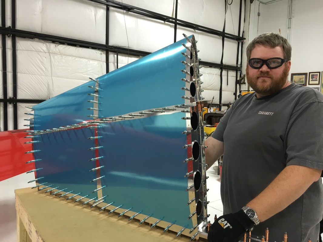 For a moment, it really looked like an airplane! Then...Mike took it all apart. See, the thing is that even though the kit comes prepunched with all of those little rivet holes, the holes aren't actually the right size. They are all just slightly too small and have to be "final drilled" to the correct size. Mike explained why the make the wholes to small but I won't go into that right now. Then, once all the holes are drilled to the correct size, they all have to be deburred. And all that work completed exactly two steps in the construction manual. 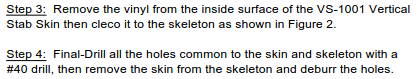 After reading that, I also just learned that the annoying blue plastic film is correctly referred to as vinyl. Finally, all of those holes on both the skin and the skeleton have to be dimpled so that all the pieces sit together properly. You might remember when I talked about countersinking pieces in a previous post. Dimpling is a very similar process, except the pieces of metal are much thinner so you don't have to use a drill to remove the excess metal. Instead, you use a dimpling die to press a little divot into the surface of the metal. This is where the head of the rivet will sit so that it's flush with the surface. Mike's friend, Keith, helped out with the build that day so I have to admit that I can't provide a lot of details on how it was done. I'm sure I'll get to help with it at some point in the future so I'll talk more about when that happens. Here are some pictures of Mike and Keith at work. At the moment, we are back to a pile of pieces on the workbench. There's a few more hours of work to be done before we put the whole thing together (again) and rivet the skin into place. 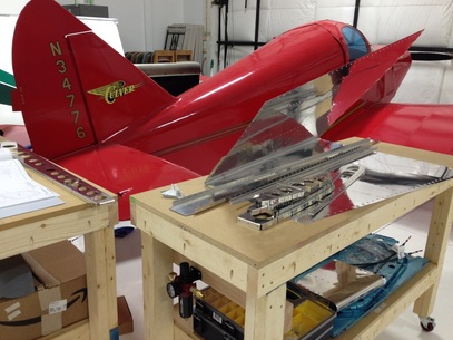 Looking less like an airplane. Also, a nice bonus shot of the Culver in the background. New Vocabulary:
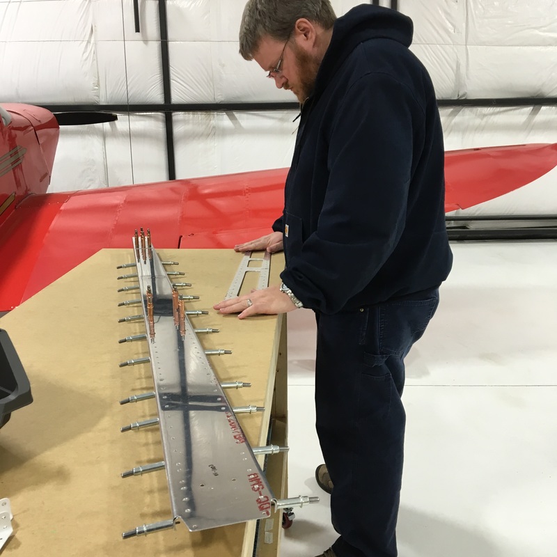
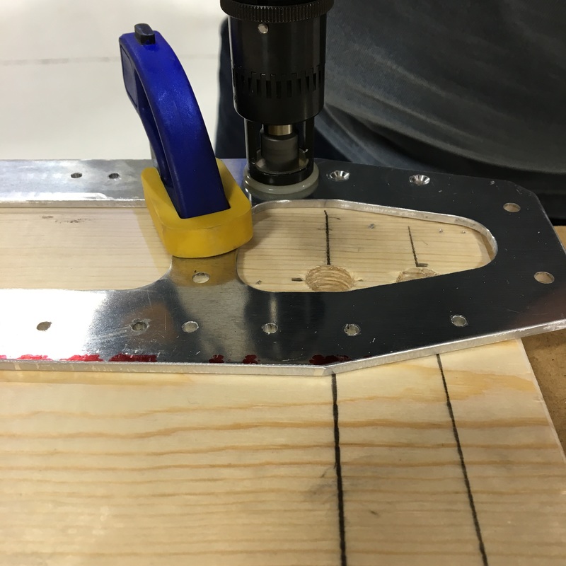
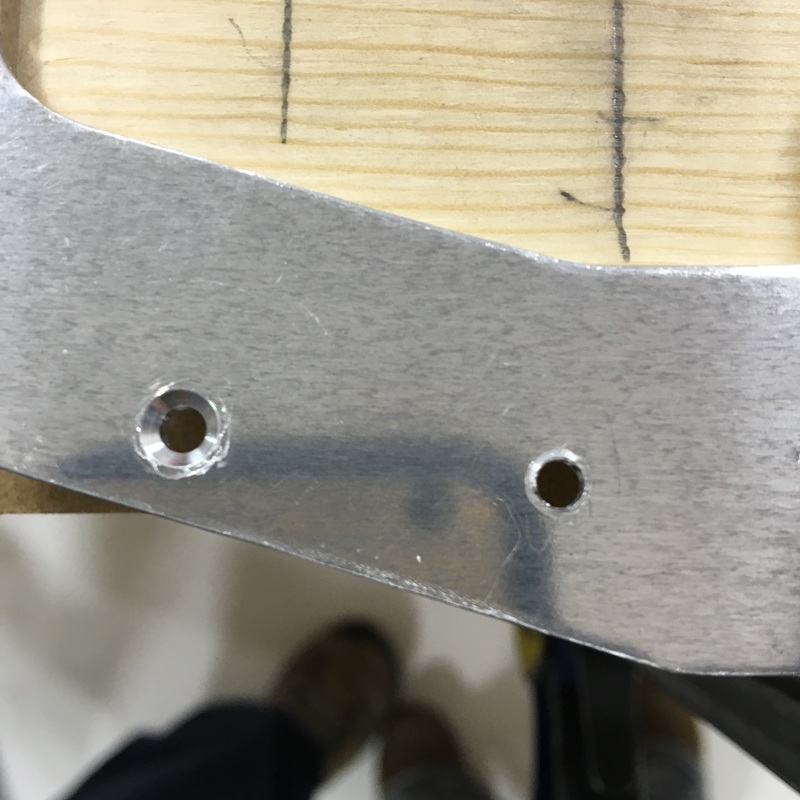
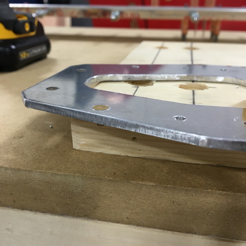
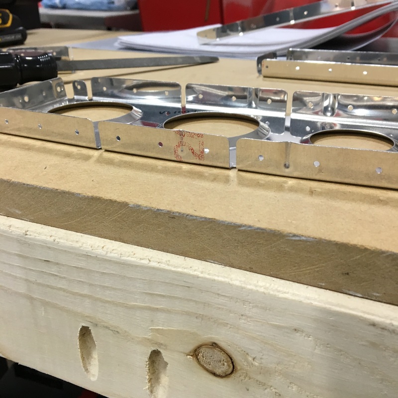
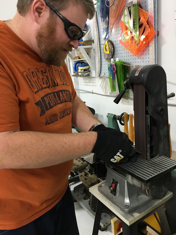
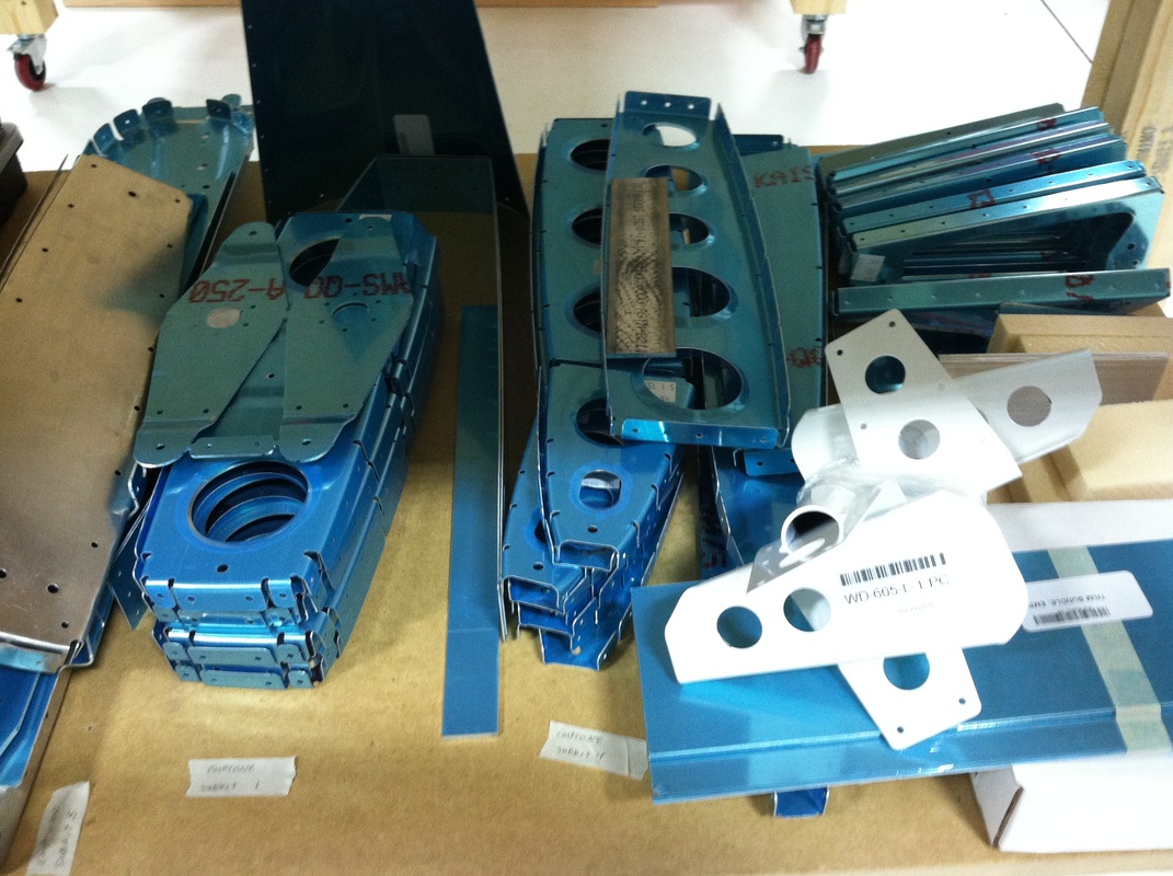
Skeleton - the inside, structural part of the airplane that you don't see Skin - the outside surface of the plane that you do see Final Drill - drilling all the holes to the right size Vinyl - the protective blue plastic that covers every since piece of the plane Dimpling - putting a small divot in sheet metal so the pieces will sit together properly and the rivet head will be flush to the surface This week we started building the airplane! Just typing that sentence is exciting (and a little bit scary). Mike has been dreaming of this project for years but this is still pretty new for me. It completely astounds me that you can build an airplane from scratch. The building starts with the vertical stabilizer, which is part of the empennage (or tail section) of the plane. (I'm so proud right now that I spelled empennage right on the first try!) The vertical stabilizer (or vertical stab if you want to sound knowledgeable) is the fin that sticks up on the tail. The instruction manual calls this section 6, which I don't understand because it's the first part of the airplane that you build. 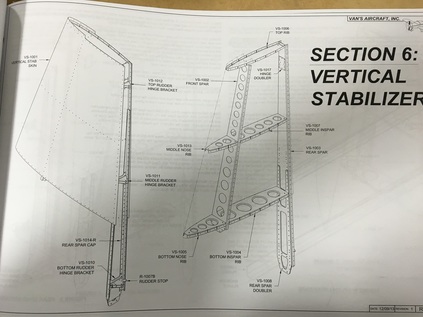 We started by putting together the rear spar - the straight upright section you see in the picture above. A spar is the load bearing portion of the aircraft, so the rear spar is made up of a bunch of different parts including a thick reinforcing piece of aluminum. This reinforcing piece was a lot harder to deal with than the other parts. In the picture below (upper left), you can see Mike trying to remove a bow that was left over from the manufacturing process. The spar is the long piece on the bench with all the clecos in it. Eventually, the spar will abut another section of the tail, so all of the holes need a countersink so the rivets sit flush to the surface and don't rub against the other pieces. Mike used a special drill bit (also called a countersink) to remove some of the aluminum and create a hole for the head of the rivet to sit in. Below (upper right) you can see the countersink Mike drilled out on the left hole. In the bottom left picture you can see how the head of the rivet sits flush with the surface of the metal. Once that was done, that reinforcing pieces is held in place with clecos. FYI - the different color clecos indicate different size holes. Holes with copper clecos are bigger than holes with silver clecos. (I would also like to acknowledge that I have no idea if I'm using the word "countersink" correctly. It seems to be a noun, a verb, and a tool all at the same time.) Once that was done, we spent the rest of our evening prepping the other pieces for assembly. Prepping pieces involves lots of steps: 1. Locate all the pieces that you will need for the next step. This involves digging through boxes and piles of pieces trying to find something labeled VS-1005. You might remember that when we unloaded the crate and inventoried the empennage pieces, there were some groups of parts that were labeled as subkits. During the process of pulling pieces for the vertical stab I realized that those subkits mean absolutely nothing! The parts that you need for a single step are likely found in 2 or 3 different subkits. I even had to pull out the inventory list again to locate where we had stored some of the pieces. This was the point when I realized that the VS I read over and over on the inventory list indicates pieces of the Vertical Stabilizer. 2. Remove the protective plastic film from the pieces. The label that identifies each piece is stuck to the plastic so you have to be write the number of the pieces with a marker. 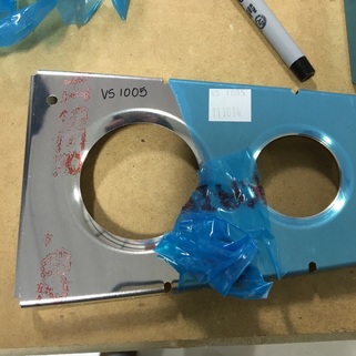 3. Deburr all the edges. We are still experimenting with methods of deburring - so far we've tried three. My favorite so far is using a regular old file to smooth the edges. That seems to work best with long, straight edges. The other method I've personally tried involves using a special deburring tool. The tool has a sharpened blade that you use to shave off a very small sliver of metal. This head swivels so it's really good for curved or oddly shaped edges. Mike has also used a deburring wheel that he attaches to a angle grinder. It's basically just a tiny, fancy grinding wheel. We refer to the deburring process as "making glitter" because you end up creating a small, sparkly pile of aluminum shavings. 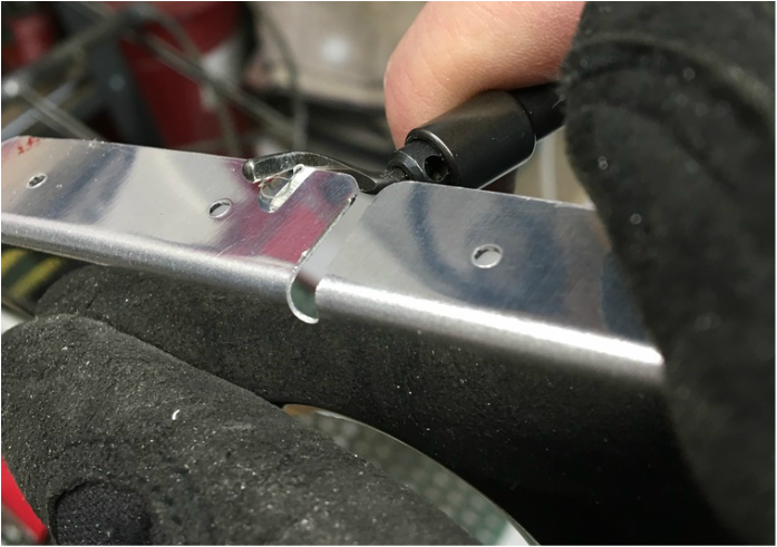 4. Straighten the piece. When they form the sheets of aluminum in the parts, things can get a little wonky. The most common thing we had to do on these pieces is flute some of the edges. You use special fluting plier to put little bends into the flange (the short parts that stick out at a 90 degree angle) so that everything sits flat again. In the series of pictures below you can see the process. Sometimes you also have to bend the flange and return it to the proper 90 degree angle. 5. Put the pieces together with clecos. This is the best part because you can actually see that you're making progress. 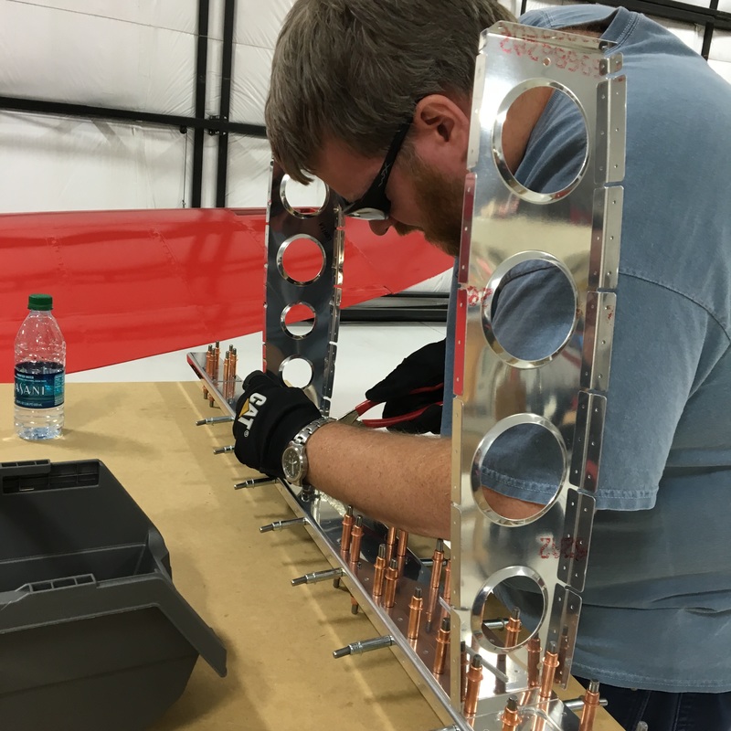 At the end of the night, we actually have something that looks like it belongs on an airplane!  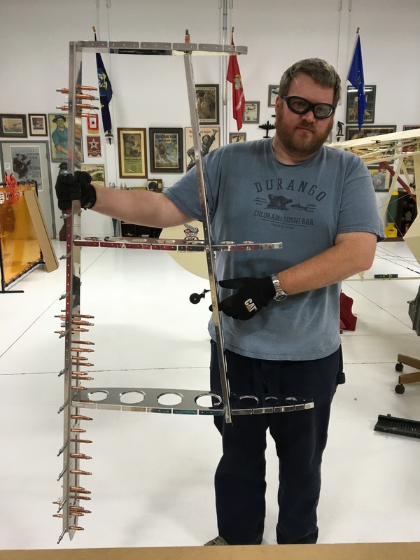 New Vocabulary:
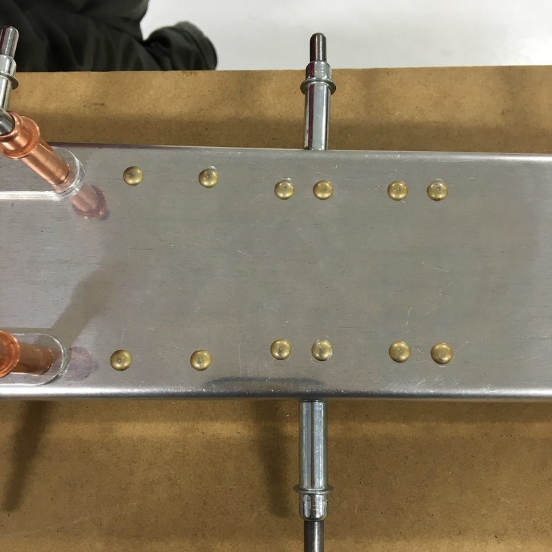
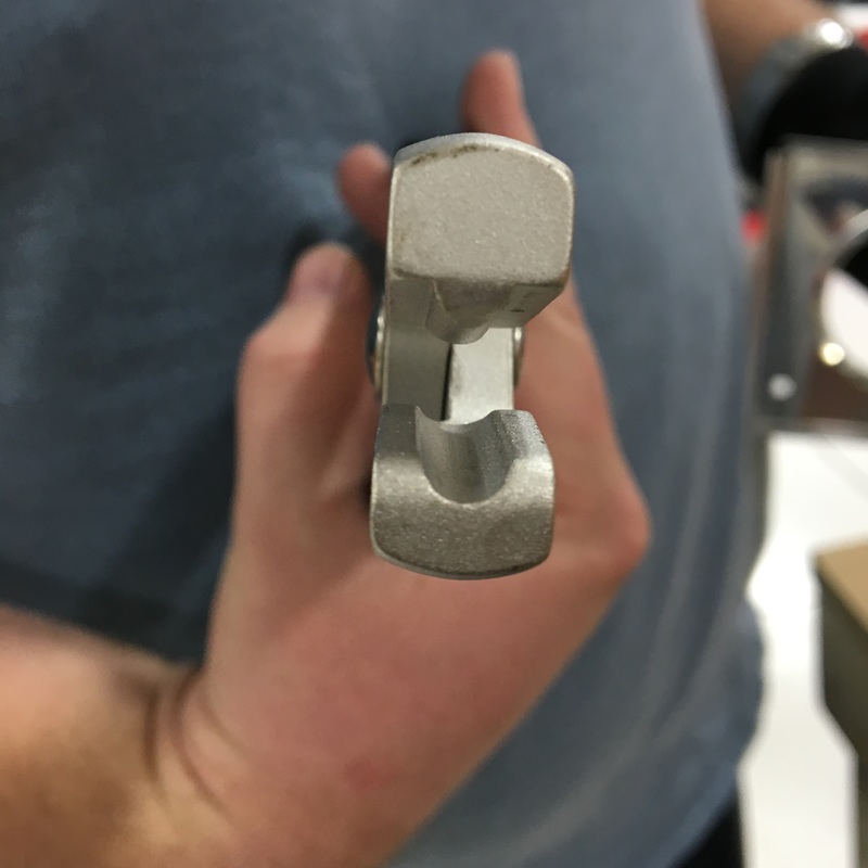
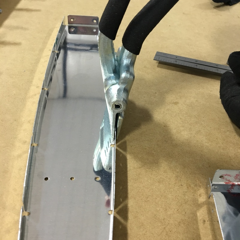
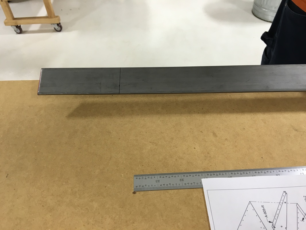
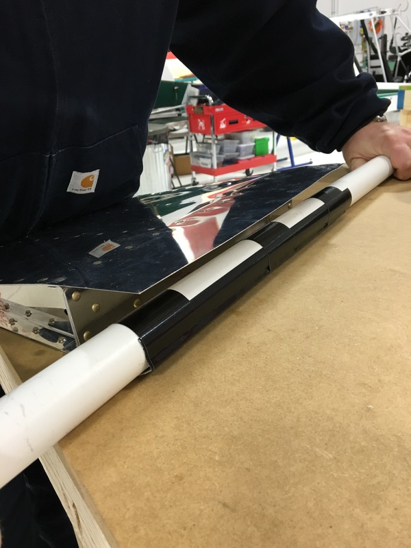
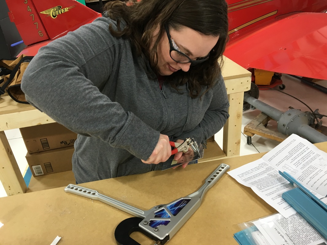
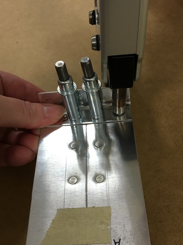
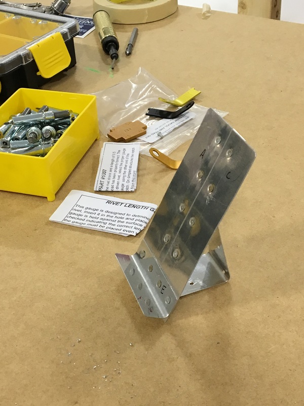
Vertical Stabilizer - the fin that sticks up on the tail of the airplane Spar - a load bearing part of the plane Countersink - making a funnel-shaped opening at the end of a hole; allows the head of the rivet to sit flush with the surface Fluting - making little bends (flutes) in a material; subtly alters the shape of the part to remove bows from the manufacturing process Flange - small section that sticks out and is used to fasten pieces together Progress on the plane has been slow over the holidays. Mike is really eager to get started on the plane but we spent a couple of weeks working on one final practice kit. There are about a thousand different skills that we'll be using when we start our actual build. These kits help us figure out how to use the tools and work out any kinks in our process before we touch the actual (expensive) airplane parts. This time we were practicing a section of control surface, which is a fancy way of describing the moving flaps on the wings and tail. I think we were working on an aileron (the section on the back side of the wings that moves up and down). When we worked on the phone stand kit, we did squeeze riveting where we used big pliers to manually squish a rivet into the shape we want. On this kit, we also got to buck rivets and use pop rivets. Bucking rivets is kind of fun but also more challenging than I expected. It requires using a pneumatic rivet gun smash a rivet into a bucking bar (basically a big, solid piece of metal). If you've done it right, the manufactured flat head of the rivet will sit flush against the metal and the shop head (the part of the rivet you smashed) will be the right shape to hold the two pieces of metal together. You can see an example of a perfect shop head in the picture. You can also see why we have to dimple the metal before riveting so that everything fits together correctly. 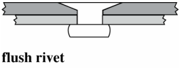 Mike did most of the prep work on this project so I got to miss out on the super exciting process of drilling and deburring holes. I'm going to have to figure out a way to make all that prep work more enjoyable because it probably takes twice as long to prep the pieces as it does to actually put things together. Mike also had to fabricate a special modified bucking bar that is narrow enough to fit into tight spaces. It also has a hole drilled into it that you can use to dimple metal if you're working in tight spaces where you don't actually have enough space to use a dimpling tool. Mike says this is called a countersink. We used clecos to hold the pieces together and then bucked a bunch of rivets. For the most part, Mike ran the rivet gun and I held the bucking bar. I like bucking rivets because it's kind of an art. You have a bunch of different bucking bars to choose from and you have to try to find one that will fit into the space where you are working and hold it just right so you smash the rivet evenly. The bucking bars are pretty heavy so they will smash the rivet as they rebound and hit the rivet. We remove one cleco at a time and put a rivet in every other hole. Then we can go back and make a second pass to finish riveting all the holes. The aileron is shaped kind of like a sideways tear drop. It's curved at the front and comes to a point at the back. Putting everything together was kind of like making a sandwich where the metal skins make up the bread and the filling is air and other support structure. The first side we riveted was pretty easy but once we put the second skin on things got really cramped. The space between the two skins is only a few inches at the widest point and I had to try to hold a bucking bar up against a rivet I couldn't see. Below you can see me with my arm wedged inside the structure. On the trailing edge (the tip of the tear drop) we only had about a quarter inch between the two sides. We tried to use the thin bucking bar that Mike made earlier but it just didn't have enough heft to smash the rivet...so we improvised. We ended up using the rest of the 3 foot steel bar that was left over earlier. I was able to press on the end of the bar and we could get enough leverage to create a shop head, although it wasn't very good. We tried the same approach with the rivet on the opposite skin but there was just no room (see the upper right picture below). After trying several different approaches we decided to just use a pop rivet in that corner. It wasn't the greatest solution but we were pretty frustrated at that point. Once the sides were riveted, Mike was able to finish the trailing edge. The final step was to finish the leading edge (the curved part of the tear drop). You can see in the picture above that the two skins are completely flat. We had to bend the front edges so we could join them together. This was a very high tech process involving a length of pipe and some duct tape. Basically, you tape a pipe to the edge of the skin and roll everything up to create a curve. It was really easy to bend the skins using this technique. Actually, this fact is kind of scary because I can see how easy it would be to accidentally bend a really expensive pieces of aluminum. Once the two skins were bent, we were able to pop rivet the two edges together. 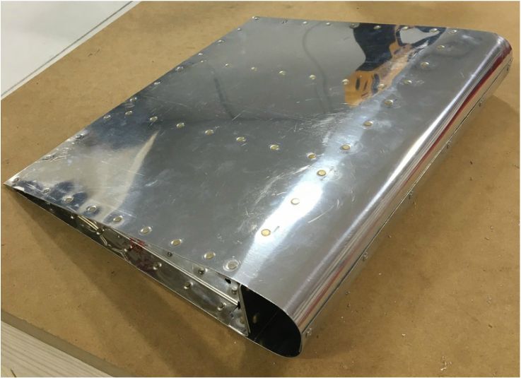 The finished project. It was exciting to see a finished product that actually looks like it belongs on an airplane. It also means that practice is over and it's time to start work on the actual plane. We pulled the pieces that Mike will need first and now the building can begin!
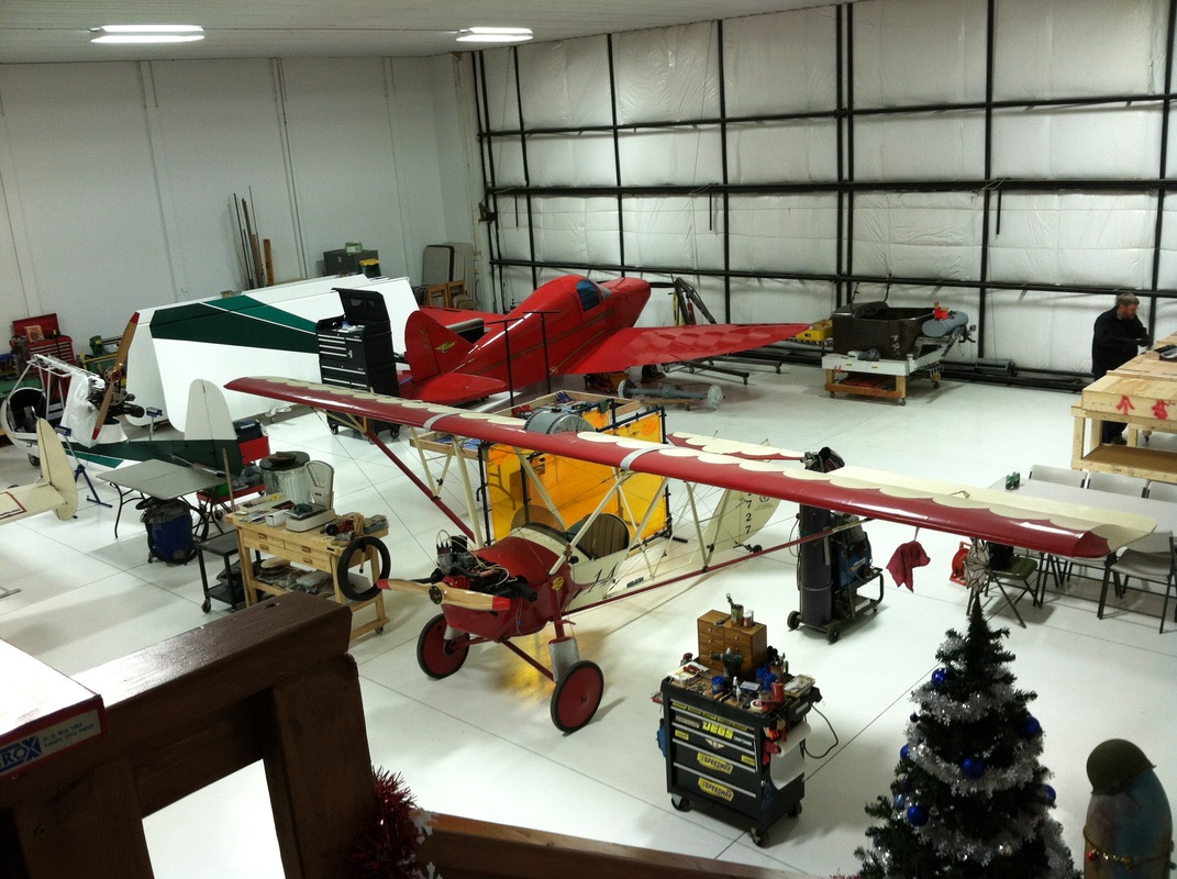
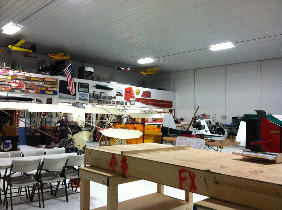
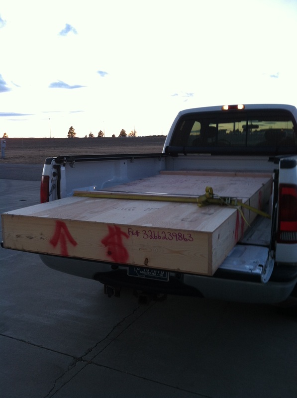
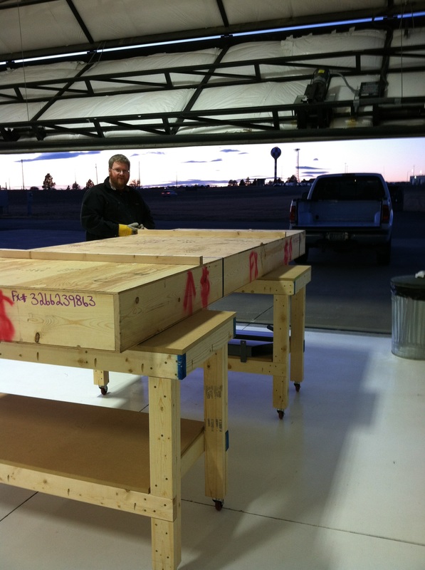
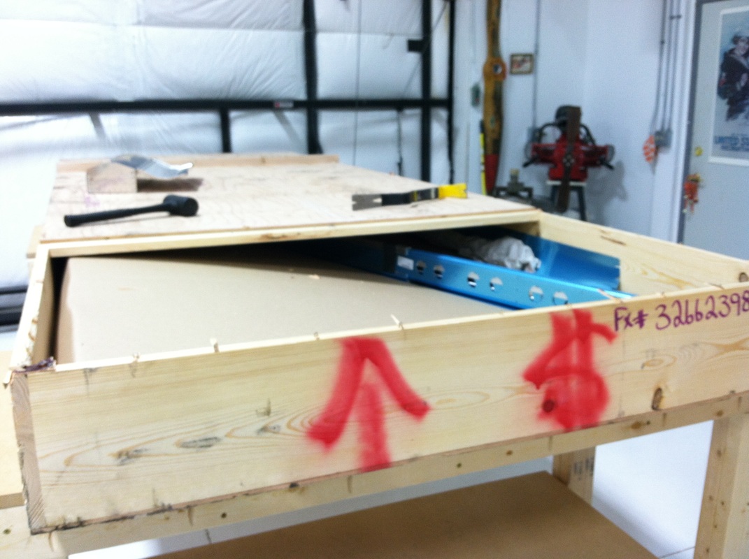
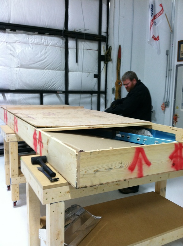
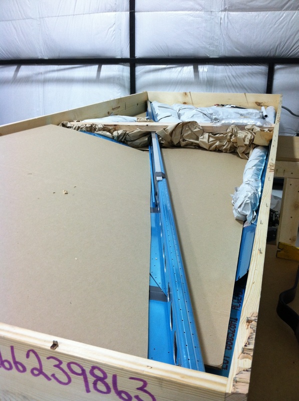
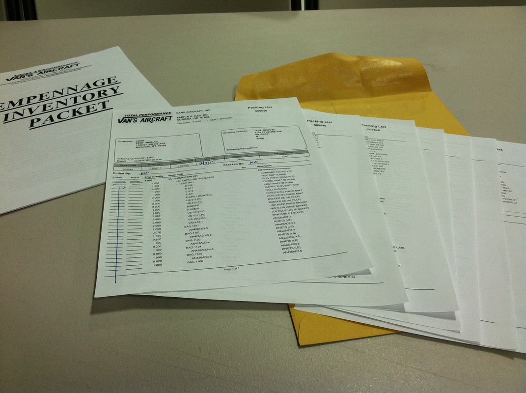
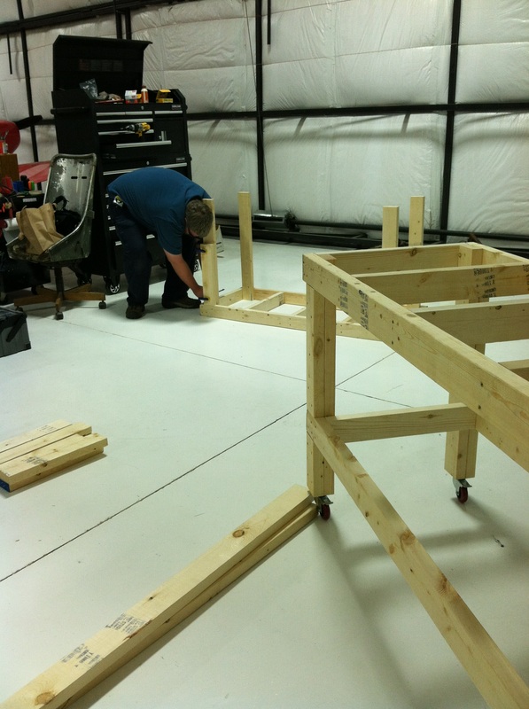
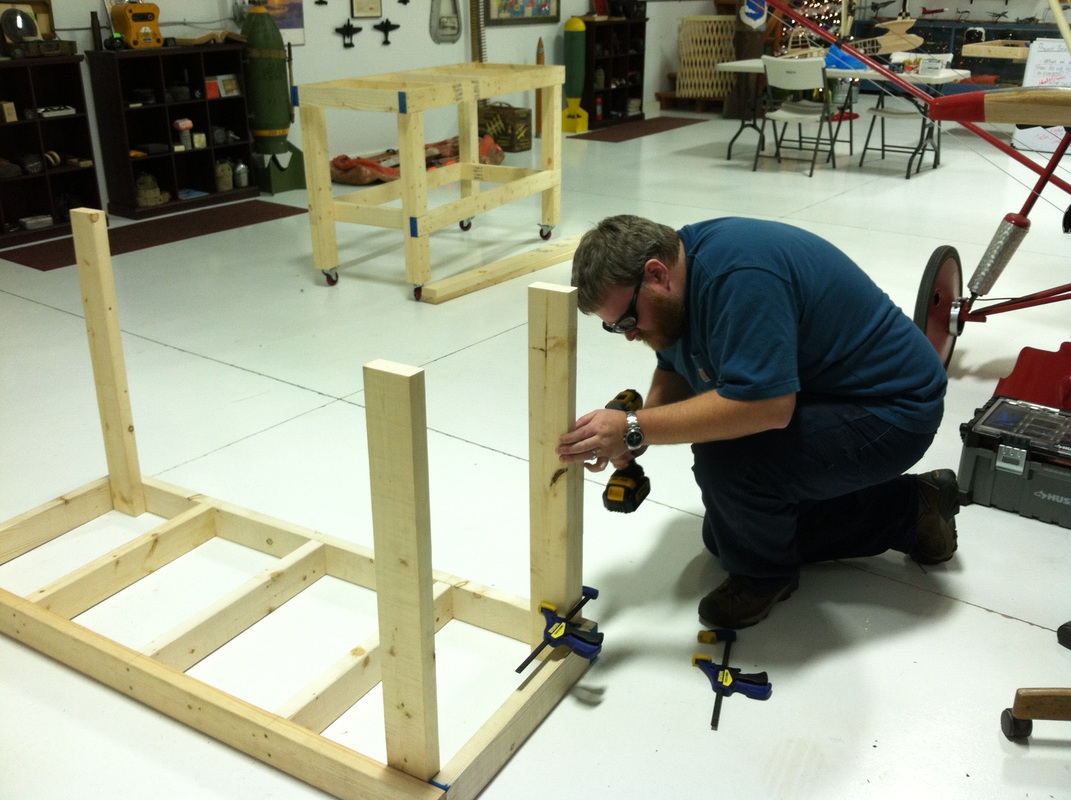
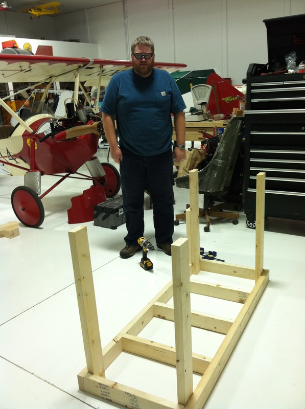
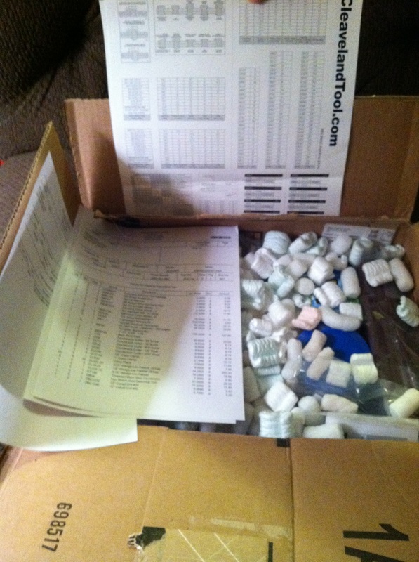
It's been a pretty slow week without much visible progress on the airplane. Eight inches of snow on Monday night and colder weather didn't exactly motivate us to spend time at the hangar. The other problem is that we needed to figure out how to store all the pieces we unpacked last weekend. The smaller structural pieces were easily put into boxes and labeled. The skins (those are the big pieces of aluminum that make up the outside surface of the plane) won't be needed for a while and take up a lot of space. The hangar where we are building is big, but as you can see it's pretty full at the moment. The best place to store the skins was up on the mezzanine (which you can kind of see in the right picture below). That required moving a bunch of other random stuff that is also being stored up there. Mike has also spent a lot of time this week reading the instruction manual that came with the kit. There are 40+ pages with directions like this: 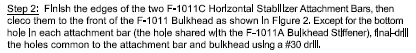 Not exactly riveting reading (oh dear, now I'm using airplane puns) and the manufacturer suggests reading the instructions 3 or 4 times before you start building. Last night, we finally got to use some of the tools that arrived a few weeks ago. Mike and I put together a small practice kit that showed up in one of the boxes of tools. Mike has done some other practice kits in the past so I've heard him talk about the steps required to fasten two pieces of metal together. I just didn't realize how many (kind of tedious) steps were involved. 1. Prepare the parts you will be using. This includes peeling off the protective blue film that you can see in many of the pictures I posted last week. Most parts are labeled with a paper sticker that lists the part number. This sticker is attached to the blue film so you have to be sure to transfer the part number onto the aluminum with a sharpie. I can't even imagine how horrible it would be if you forgot to transfer the part number since most of the pieces look nearly identical. 2. Deburr the edges of each piece. Deburring is the process of removing tiny pieces of metal that are left over from the manufacturing process. These tiny metal pieces make any cut (or drilled) edges sharp and can cause problems later. 3. Drill the rivet holes to the appropriate size. The pieces come predrilled, but the holes aren't quite big enough (for reasons I really don't understand). (Picture 1) 4. Deburr the holes that you just drilled. 5. Repeat this process for every single piece you are going to be using. 6. Dimple all those holes that you just drilled. You use flush rivets when you build an airplane so you have to create a little hole for the rivet head to sit in. That's what the dimpling tool does. 7. Join the appropriate pieces together using clekos. Clekos are special fasteners that are used in airplane manufacturing. There are several types of clekos but the most common seems to be a metal cylinder with two pins inside. As you press down on the top plunger, those pins extend and come together so they will fit through the hole you just drilled. When you release the plunger, the pins retract and spread apart to hold the pieces of metal together. You have to use special pliers to install and remove clekos. (Picture 2) 8. Remove the appropriate clekos and install a rivet to hold the pieces together. There are several ways to rivet but last night we used a squeeze riveter because we didn't feel like dealing with the air compressor. The squeeze riveter is kind of fun and was my favorite part of the process. You put the rivet into the hole and then use the tool to squish the rivet into the right shape and thickness. You can actually see the metal in the rivet deform and squish to form the end that holds the pieces together. (Picture 3, 4 & 5) I can see the squeeze riveter being finger smasher because those handles come together with absolutely no room between them. There is even a little tool that you can use to make sure you've squeezed the rivet to the appropriate dimension. (Picture 6) 9. Repeat the two previous steps over and over. I would say that it took us about an hour to put the project together, mostly because we had to figure out how to use each tool. At the end of the night, I had a fancy new stand for my phone. We used it to take our first hangar selfie. The matching aprons were a Christmas gift from Mike's dad last year. (Hi, Leroy!) This is a BIG week for our household...the first airplane kit has arrived. For those who are interested, we are building an RV-10 from Van's Aircraft (http://www.vansaircraft.com/public/rv10.htm). When Mike and I were in Oregon last fall we visited the Van's factor and I got my first taste of what kit building actually means. Mike also had the opportunity to take a test flight in RV-14, which is what he originally intended to build (before I convinced him to go for the bigger RV-10). Here is a picture of us sitting in the RV-14. The RV-10 has DeLorean style doors (I'm sure there's a technical term, but you know what I mean. Mike was just reading over my shoulder and informed me that they are called gullwing doors.) and 4 seats. 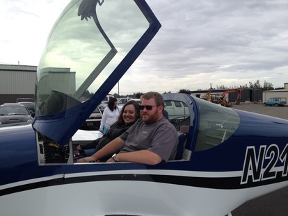 This is not the plane we are building. The empennage kit arrived in a really long, flat crate that Mike had to pick up and haul to the airport. The hangar where we are building is inside the security perimeter of the airport and Mike didn't want to deal with the hassle of getting the crate delivered directly there. The crate fit in the back of the pickup, barely. It also weighed about 300 pounds. One of Mike's friends had the brilliant idea of using our fancy new workbenches to wheel the crate from the pickup to the hangar, which worked like a charm. Then the uncrating began. Once we had the crate open, it was time to inventory all of the parts. In the lower right picture above, you can just see a bunch of paper wrapped bundles at the back of the crate. Each of these was full of parts. The people who pack up these kits must be awesome at Tetris because you would not believe how many parts they could fit into this box. The packing list was 7 pages long and actually came with instructions to explain what all the letters and numbers mean. The first three and a half pages contained all the rivets and bolts and tiny pieces of hardware that we will be using. It took us about 6 hours to inventory all the parts. Mike spent two of those hours going through the bag of hardware. Each bundle had to be unwrapped and then the pieces had to be separated and identified. Most of the parts were tagged with a number, but you had to be careful not to confuse VS-1011-PC and VS-1001-PC. The bigger pieces were taped into the bottom of the crate with some sort of industrial strength duct tape. We don't really have a storage system set up for parts yet, so everything is currently stacked up on the workbenches. At the moment, this is what our plane looks like. New vocabulary:
Gullwing doors - doors that open up, like on a DeLorean. I'd like to preemptively explain the title "Knots per hour" before someone points out that I'm using the wrong unit of measurement for airspeed and am therefore totally ignorant about all things airplane. I admit that I'm clueless when it comes to airplanes, but I have learned that airspeed is measured in knots. A knot actually means one nautical mile per hour, and is how you measure speed and distance when you're talking about airplanes (or ships). Saying "knots per hour" would be like saying "one nautical mile per hour per hour" which would be a unit of acceleration (according to Mike. I may be a bit of a math nerd, but that's not something I would ever know on my own). If you want to appear knowledgeable in the world of aviation, you always have to use the term "knots" correctly. It seems that the types of people who are into airplanes are also the type of people who really care of expressing things in the appropriate units. So, now that we all know that we should be saying knots, let me explain why I decided to use the wrong term so prominently on this website. The first reason is that "knots per hour" is an inside joke in our house. The first several years that Mike and I were together, my life was a little bit crazy. I spent our first year together planning a regional conference for a professional organization that I'm part of. Months before the conference actually happened, I also decided that it was a really great time to start grad school. During all of this I was also working full time at a stressful job, so needless to say the next few years were a wee bit busy for me. When I finally finished my master's degree, I really wanted to show Mike how much I appreciated all of his support, so I bought us tickets to see the Red Bull Air Races in Las Vegas. Let me just say that the Air Races are an amazing experience. Even with my limited understanding of flying, it's easy to appreciate just how skilled the pilots are. Now, as with any live sporting event, there can be a lot of downtime while you're sitting in the stands so there are some commentators on hand to provide information and entertainment. Two gentlemen were providing commentary that weekend. The first was very knowledgeable about aviation and the second, not so much. In the Air Races, pilots must enter the course under a certain speed (200 knots) or receive a time penalty. As each race takes around 55 seconds, a 2 second penalty can be the difference between progressing to the next round and being eliminated. The pilots are so skilled that they often enter the track at 198 or 199 knots, and for the novice spectator it's one aspect of the race that's easy to appreciate. Throughout the race, the second (less knowledgeable) commentator repeatedly (and incorrectly) used the phrase "knots per hour" to describe the pilot's entry speed. Even though the mistake had been pointed out and explained by the more knowledgeable commentator, the second commentator never did get it right. After two days of the same mistake, it became a running joke and when I was naming the blog, it seemed like "knots per hour" was the obvious choice. The second reason I think "knots per hour" is a good name is because it reflects my ignorance as we begin this endeavor. Aviation people have their own lingo and a saying something like knots per hour is the kind of mistake that identifies you as a rookie outsider. The world of aviation is full of words and phrases that I don't understand. What the heck is an "empennage"? (Thanks to Google for helping me figure out how to spell that word. This whole time I have been thinking it was epinage.) Glad you asked - that would be the tail section of the airplane. Did you know that it had its own special name? Me either! Since this blog is about an outsider's perspective on the building process, I thought it was appropriate to acknowledge my novice status. The point isn't that I appear knowledgeable about what's going on, it's that I'm learning as I go and I'm going to make lots of mistakes. For the vast majority of us who haven't been reading airplane magazines since we were kids, we can figure this whole thing out together as we go. New vocabulary:
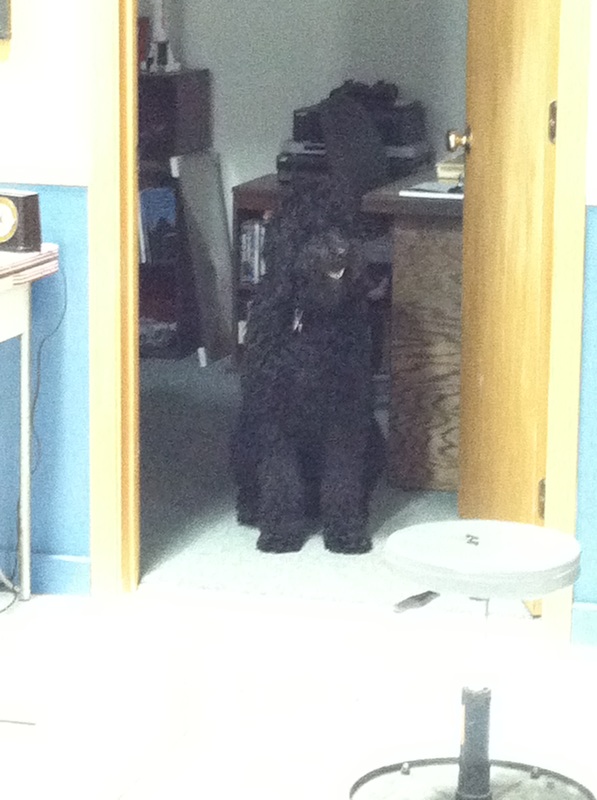
Empennage - the tail section, or rear section of the body, of an airplane. I can always tell when Mike is thinking about airplanes. His eyes become distant and he gets quieter than usual. If we are taking a walk, his pace quickens and he won't even realize that he's left me in the dust. I once asked Mike how old he was when he became interested in airplanes and it turns out that this is a life-long obsession. I, on the other hand, know almost nothing about airplanes. I've spent many hours on commercial planes and have a vague understanding of some basic principles of flight, but for the most part, aviation is a foreign language to me. Until I met Mike, I had no idea that you could actually build your own airplane. Who does that kind of thing? Apparently, lots of people build their own planes. I know this because every month we receive several magazines about home building, Mike religiously reads message boards where builders congregate, and there's even an international organization for aviation enthusiasts. I've known for years that we would build a plane someday, and now it seems that day has come. The tools have arrived, the work benches have been built, and the first kit is ordered. Mike is excited (if a little nervous about such a big undertaking) and I'm supportive but pretty unsure about what's actually going to happen. That's one of the reasons I decide to start this blog. What is it actually like to help someone build an airplane? What do I need to learn? How can I be a help, rather than a hindrance, during this process? My second reason for documenting this process is that Mike and I have friends and family scattered across the world who might be interested in watching Mike realize one of his biggest dreams. I hope that I can provide a layman's perspective during this process so we can all understand what's happening. I've posted the first round of photos below. Since these photos were taken, Mike has finished the work benches and moved all of his tools up to the hangar. We will be spending a lot of time at the hangar over the next several years, so we are getting Zoey used to be up there. She loves it when some of the other guys are there working on projects and she gets lots of attention. She's less excited when people are using power tools and likes to hide in the office to escape the noise. |
AuthorThe supportive spouse's guide to building an airplane. Archives
May 2017
Categories |


 RSS Feed
