|
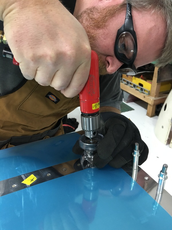
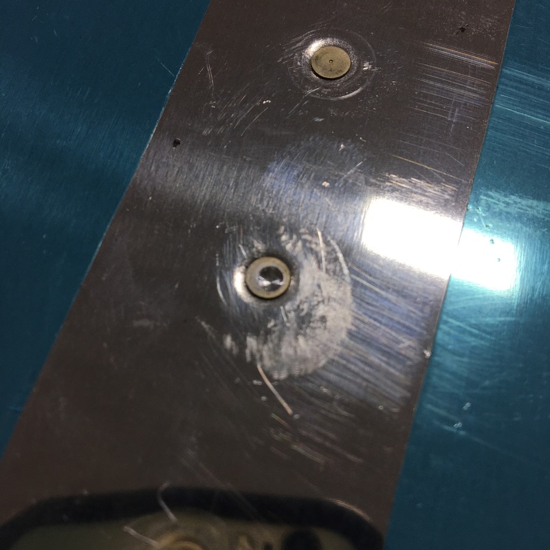
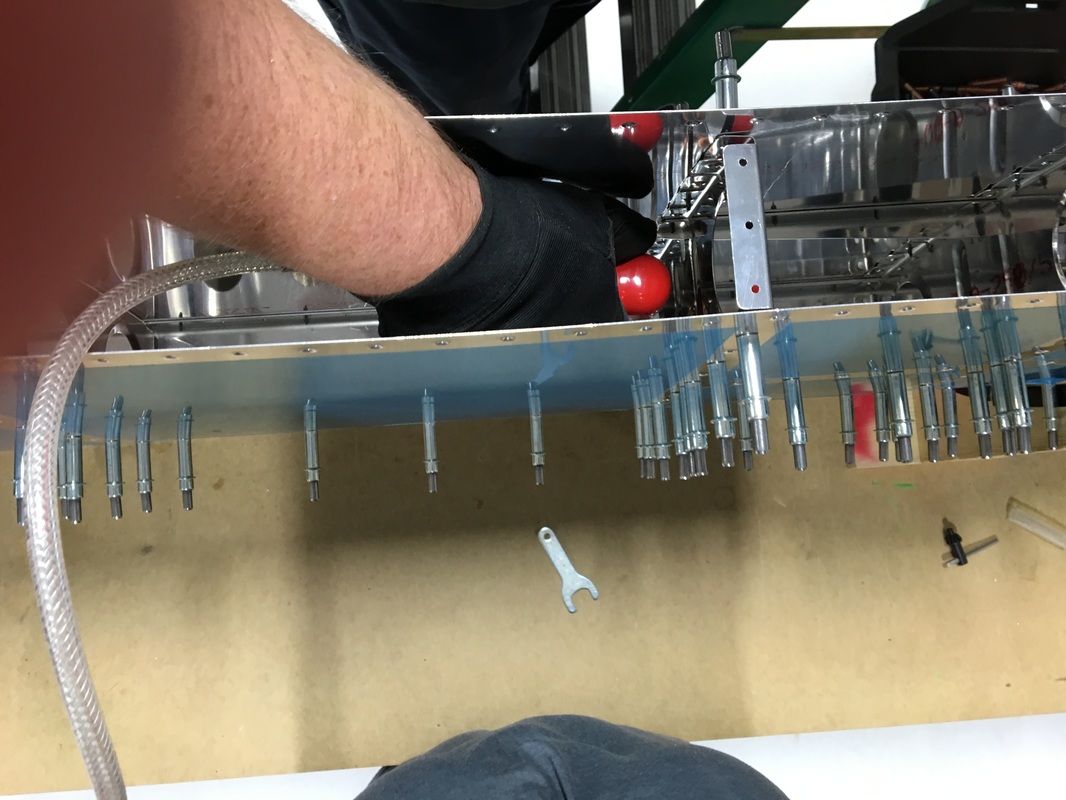
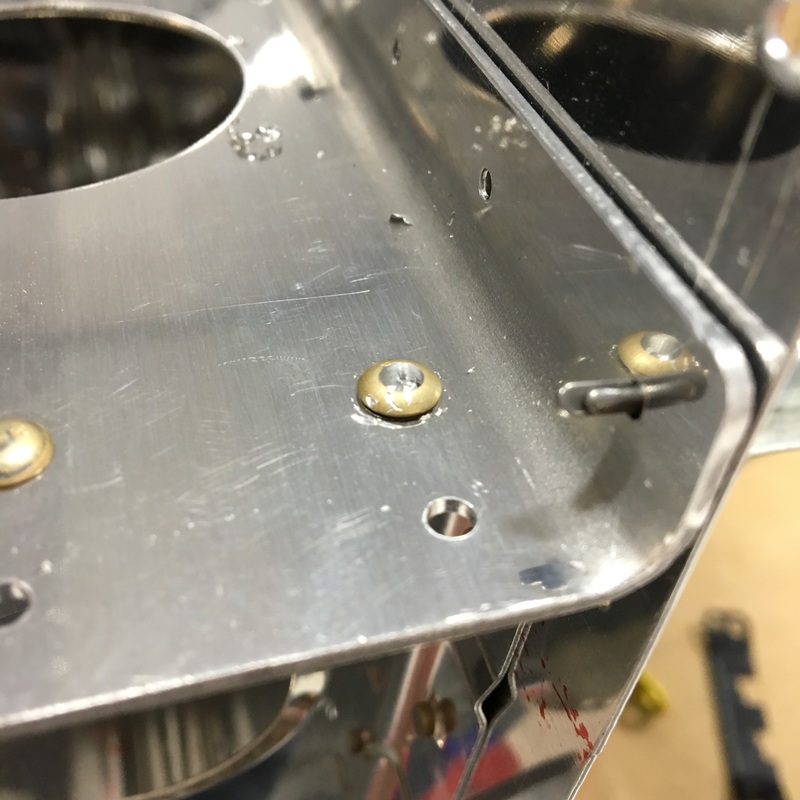
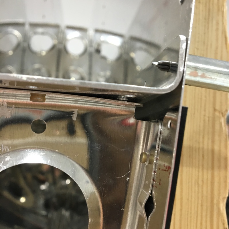
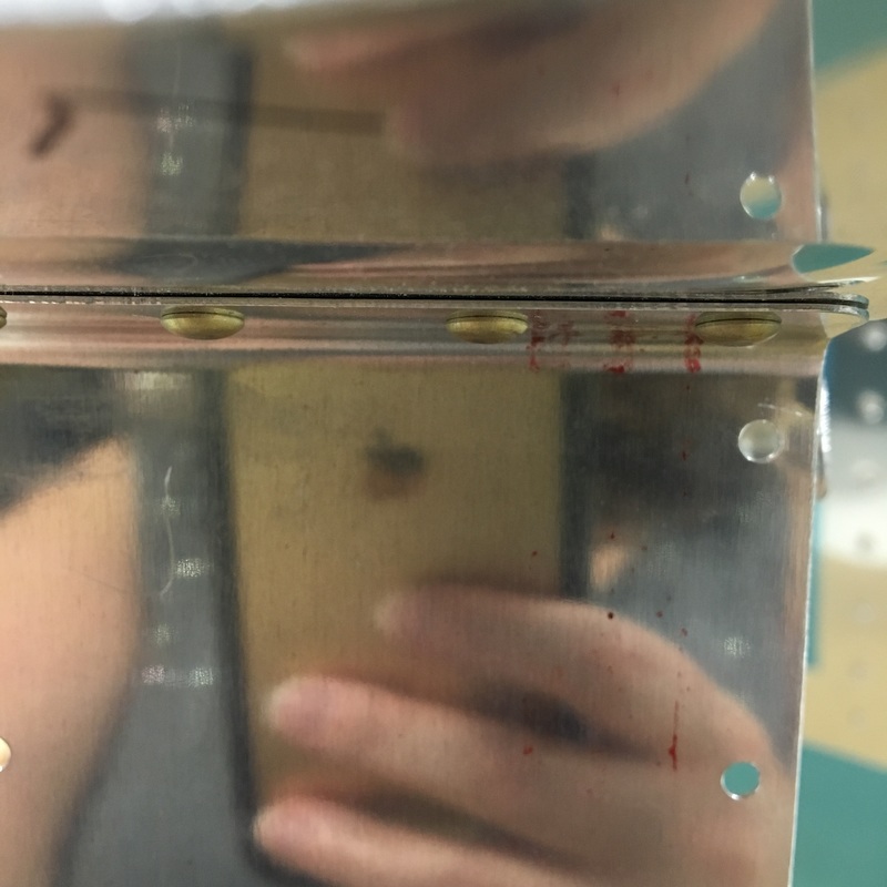
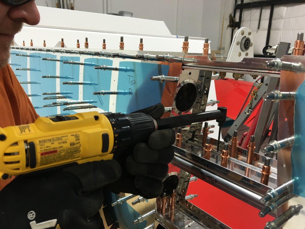
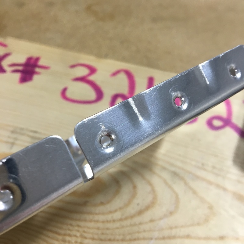
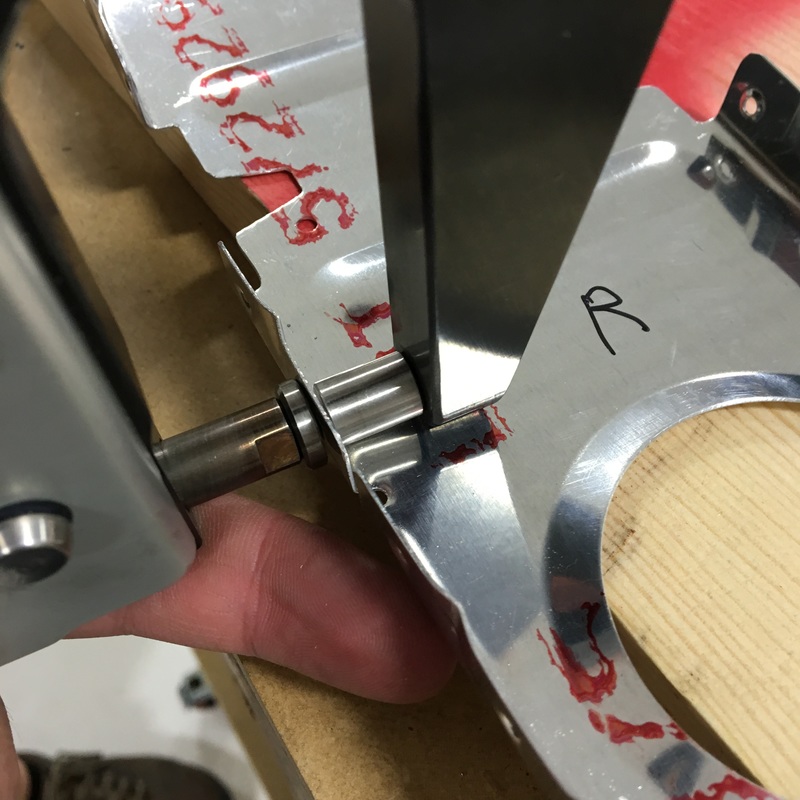
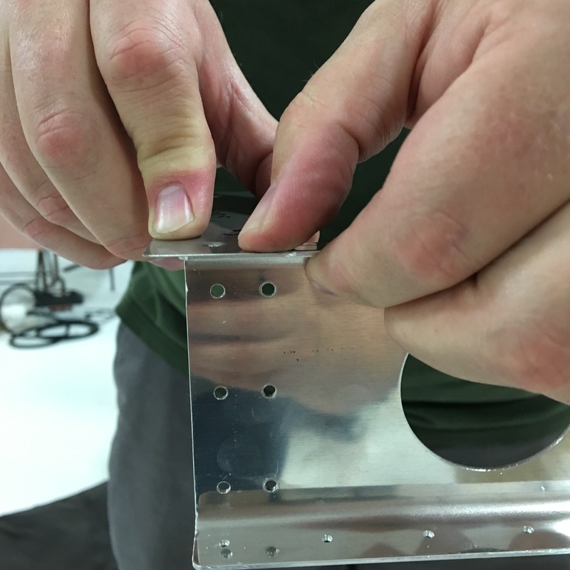
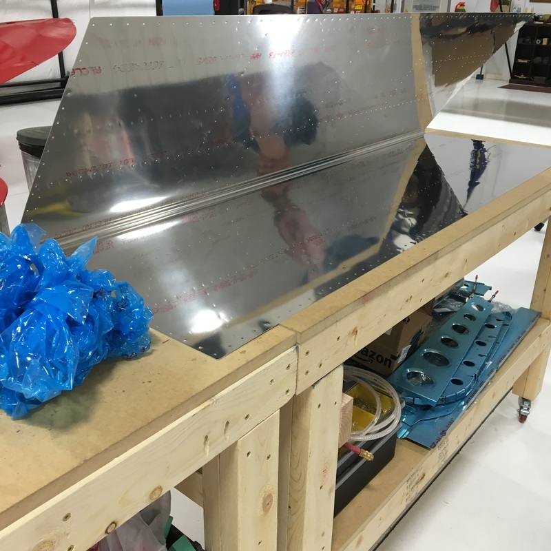
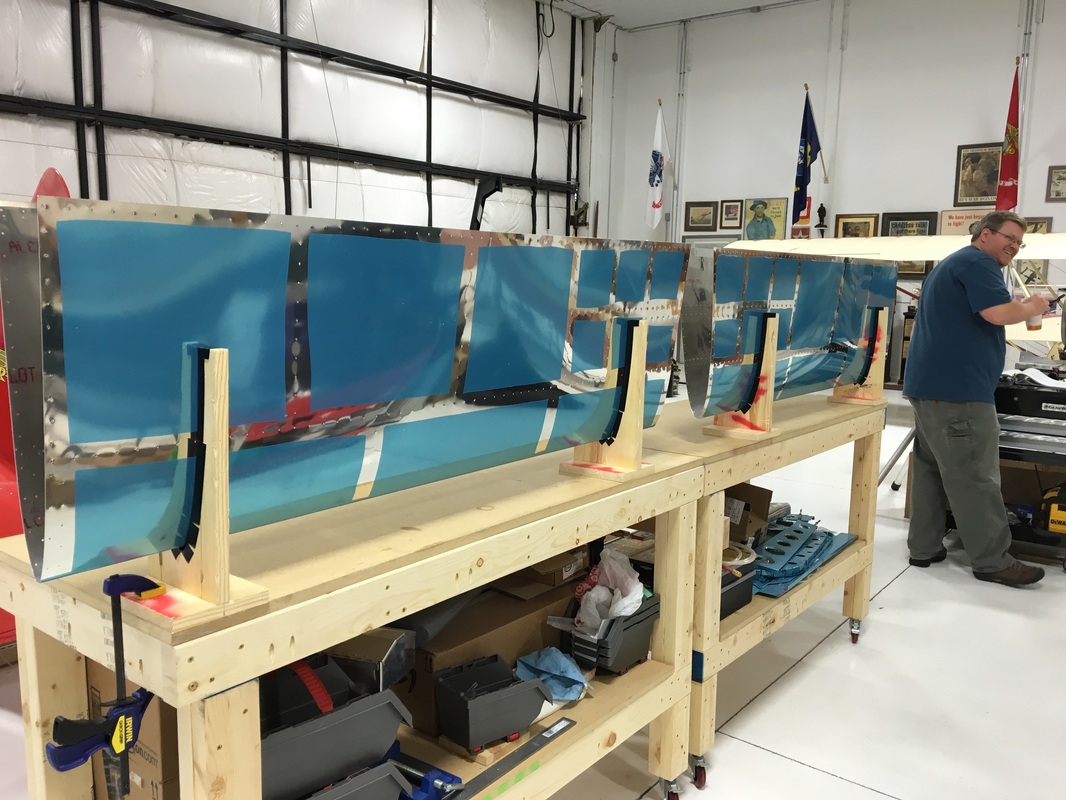
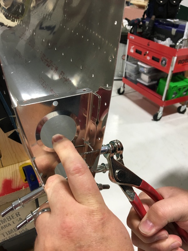
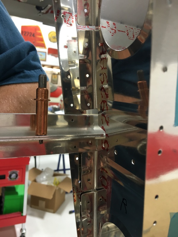
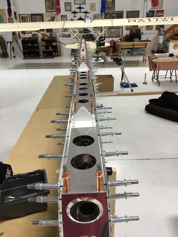
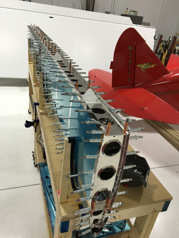
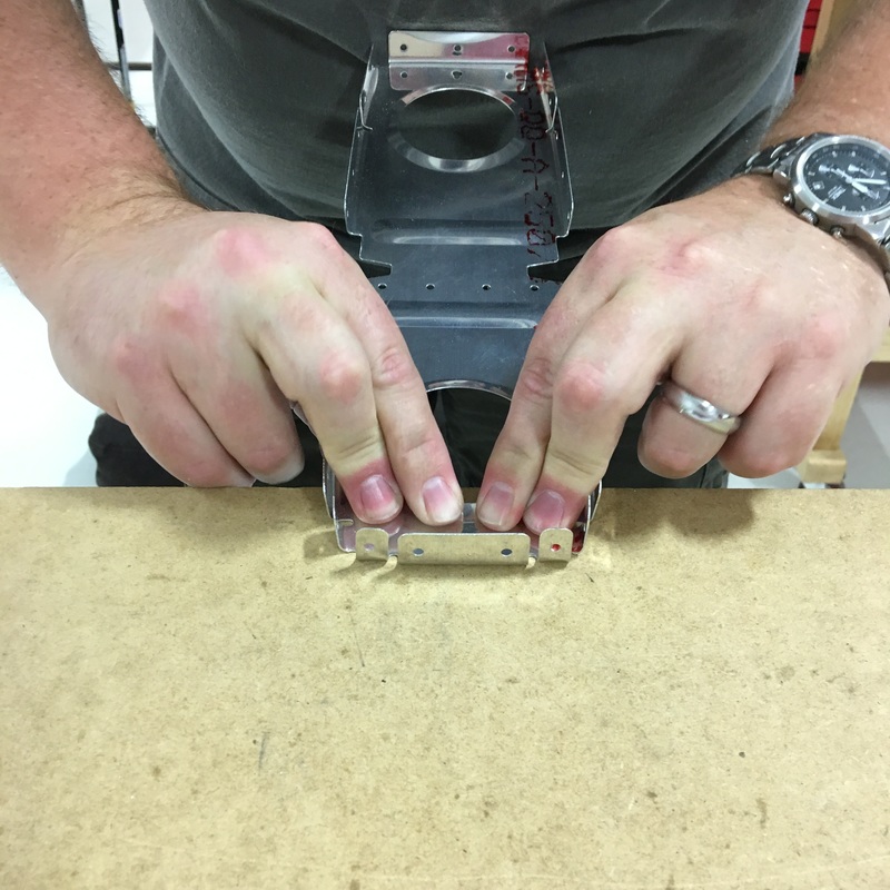
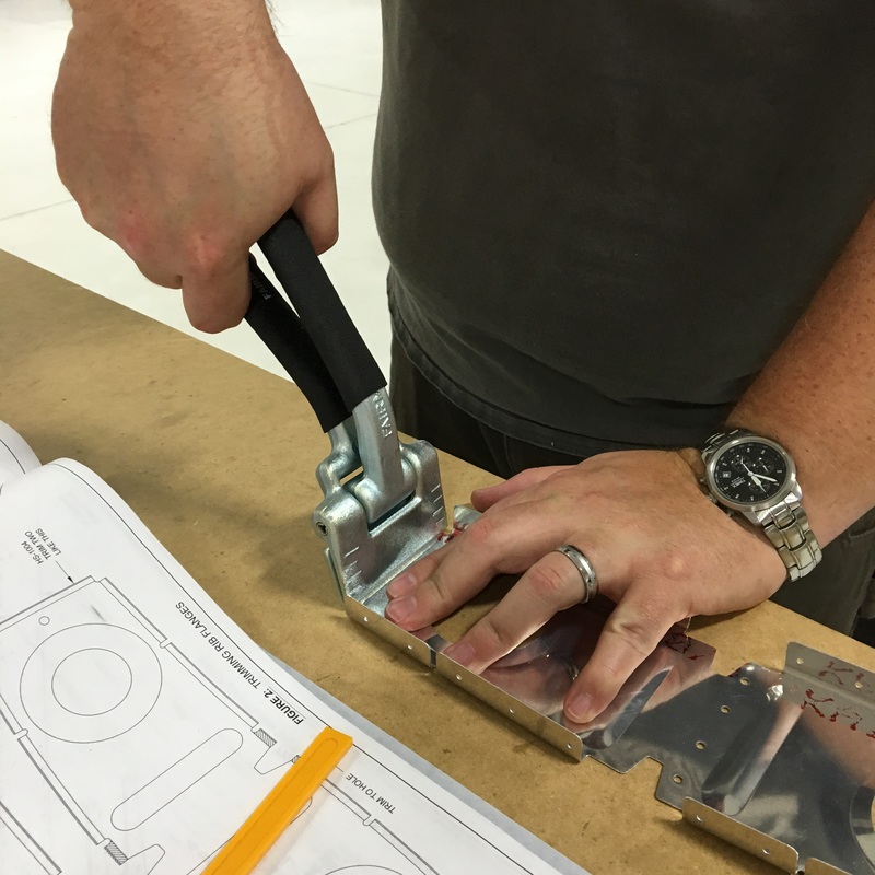
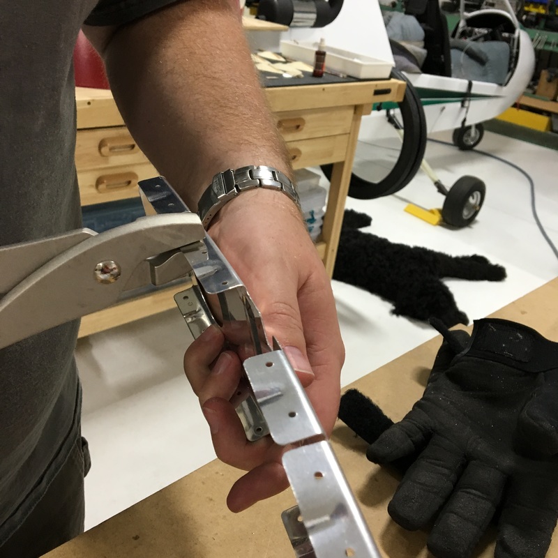
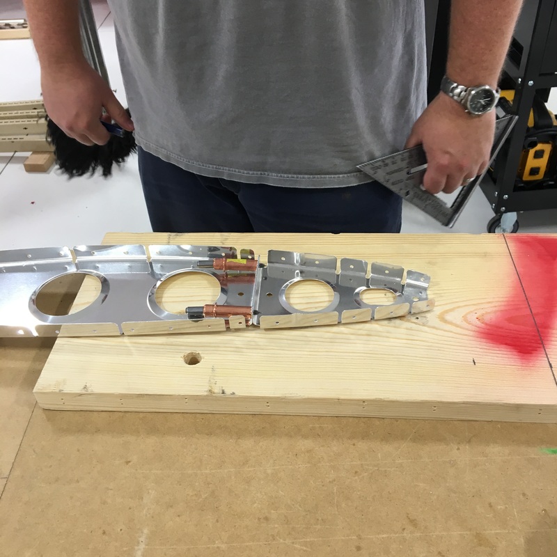
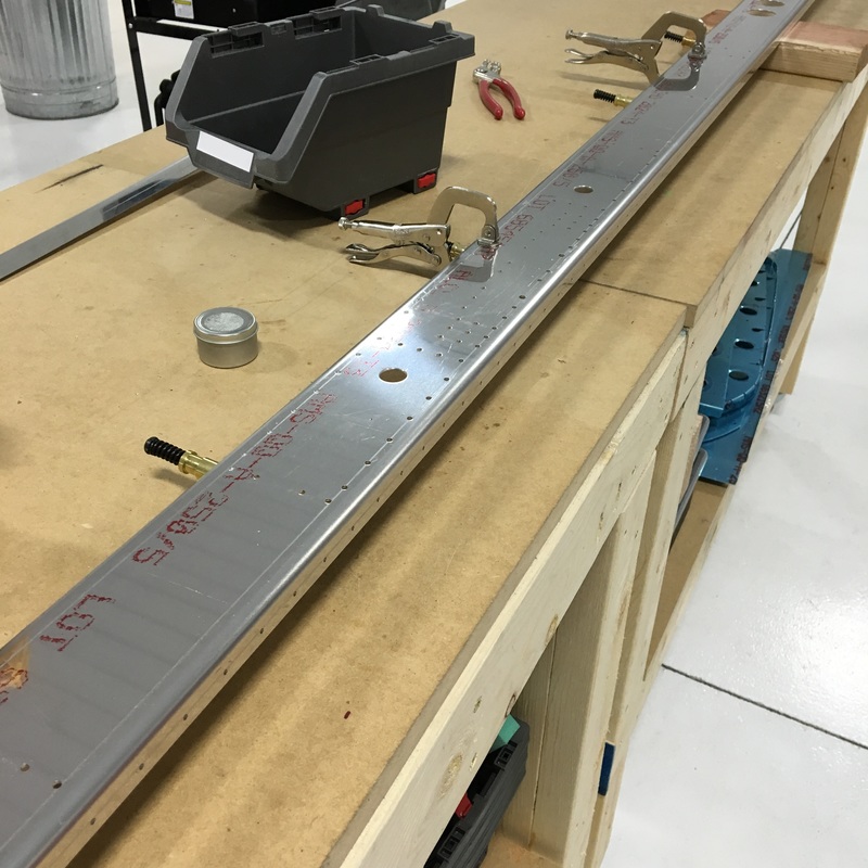
I was right, it took us 3 work sessions to finish riveting the ribs to the skin. I continued to use the long, steel bucking bar and it worked great! Everything went very smoothly, it just took time. Here we are one quarter done: 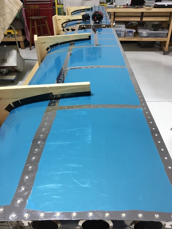 And here is one side completely finished and without rivets! 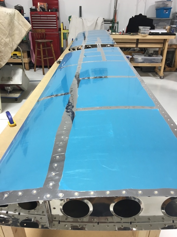 That probably doesn't seem very exciting, but the last time there were no rivets in the skin was when we first put the skeleton and skin together in August. We were also able to remove the wooden cradles we created back in June. It was really nice not to have to deal with the cradles because they tend to slide around on the bench. We used some small pieces of foam between the horizontal stabilizer and the workbench to cushion everything. The bad part about losing the cradles was that it lowered everything by a couple of inches, which meant I had to bend down farther when we were riveting. You wouldn't think that a couple of inches would make much difference, but it was a lot harder on my back and neck. We finally finished riveting the skin to the ribs this morning. Mike decided to show off his best Vanna White moves. 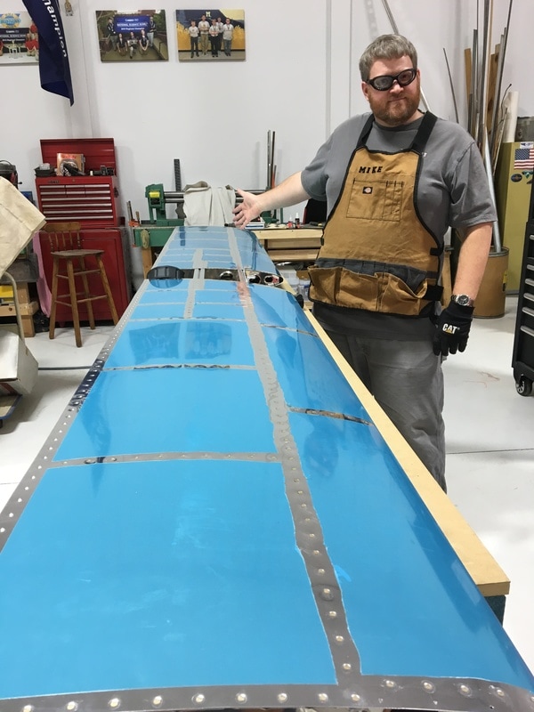 The whole thing is surprisingly light with no clecos in it. Our next task was to go back a few steps and finish riveting a rib to the front spar. When we first worked on this step many months ago, the directions suggested these rivets would be easier to access once the cradles were out of the way. 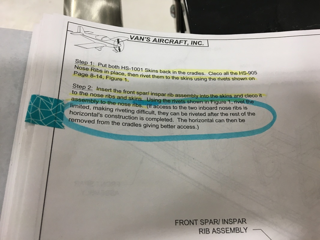 I'm going to tell you right now, the cradles are not the problem. The problem is that this space is practically inaccessible. Here's what the instruction manual shows... 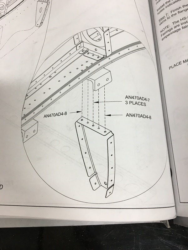 And here is where you're actually trying to work... 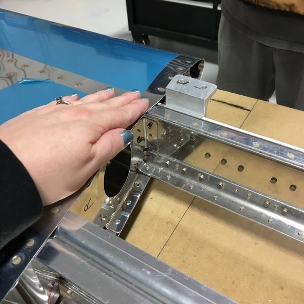 I put my hand in the picture to provide some sort of scale. You can just see the empty holes and ends of the clecos next to my index finger. (The fact that my fingernail polish matches the blue vinyl is a nice bonus.) These rivets are between the two halves of the horizontal stabilizer (right in the middle where the skin doesn't cover) and between the front spar and the horizontal stringers. My hand is pretty small and I estimate there's about six inches between the stringer and the spar. There's practically no room to work in there and because everything is at a funky angle, most of our tools wouldn't reach either. The rivets wouldn't quite fit into the holes, but Mike couldn't use the regular drill bit to ream the holes. The normal bit he uses in this situation is specifically shaped so it won't enlarge the hole, just remove any tiny chips of metal that might be blocking the rivet. Instead, he had to very carefully use a really long, regular drill bit and try not to enlarge the holes . 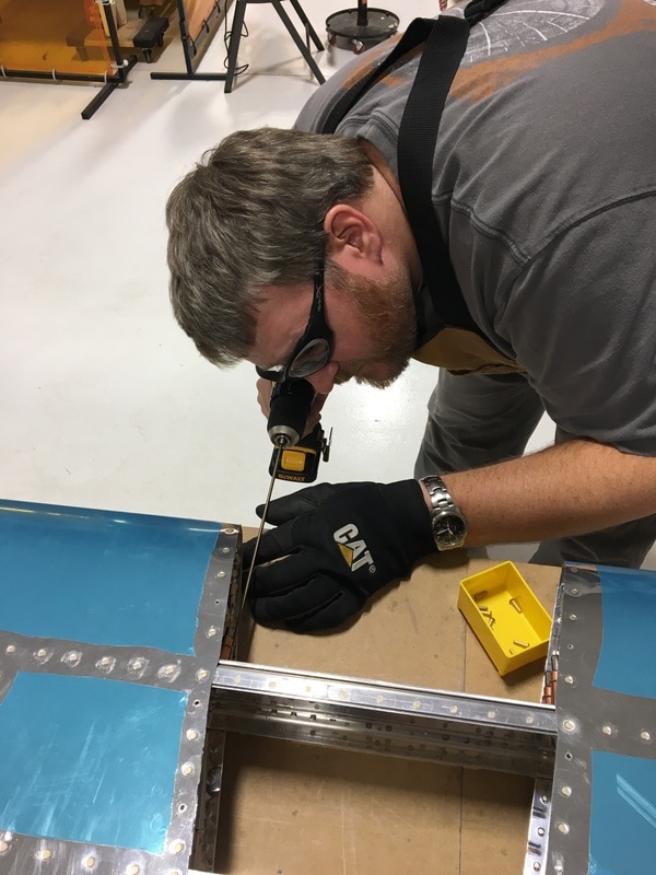 We tried to figure out a way to squeeze those rivets, but there just wasn't enough room. Mike had to use the offset riveter and I had to revert to my tungsten bucking bar because it was the only thing that would fit in that tight space. There are so many other rivets in other pieces in that area so I also had to be careful to not accidentally damage those. To top everything off, we were using size 4-8 rivets, which are bigger in diameter and a lot longer than what we've been using. I didn't take many pictures of us trying to install these rivets, mostly because I was too busy swearing and feeling frustrated. My hands and knuckles got banged around a lot and it took us about 45 minutes to put in 10 rivets. At one point, Mike actually ran the rivet gun and the bucking bar on his own because that was just easier. 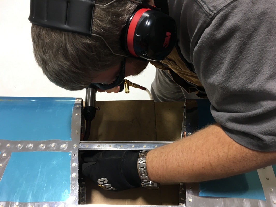 We managed to get it done, but not without one major screw-up. 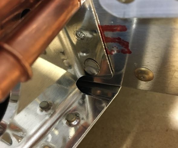 That rivet is definitely a problem. One side is basically pounded completely flat against the rib flange. It will have to come out, but that is not going to be an easy task. Normally we would drill out the rivet head and punch the shaft out the other side. Since we can't really identify the center of the rivet head, that probably won't work. We decided to leave it for now so Mike can think about the best way to get it out of there without doing serious damage. We ended the day by (finally!) clecoing the rear spar into place. We officially have no more loose parts for the horizontal stabilizer!!! We need a few more pop rivets to connect the rear spar to the ribs and then we can rivet the skin to the rear spar. 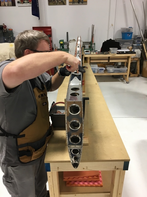 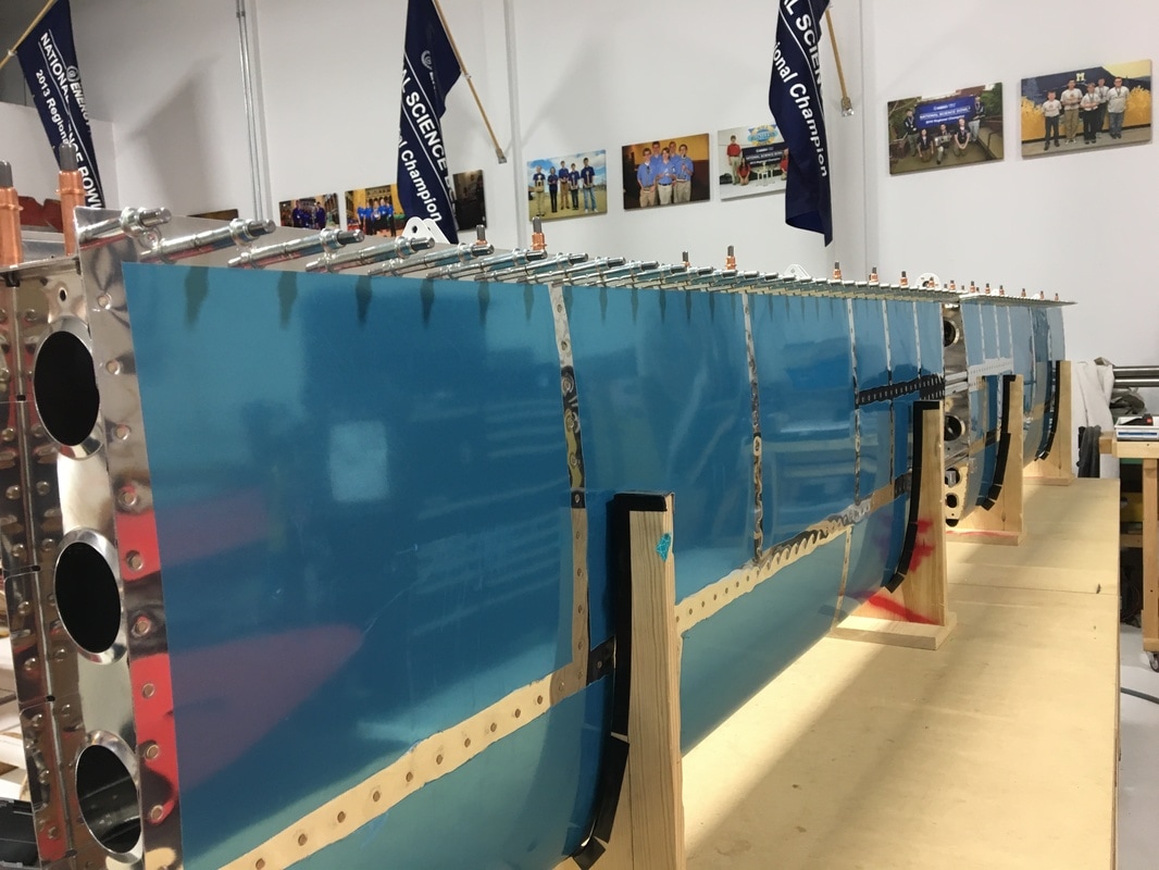 Finally, I hit a very exciting milestone today. I have personally put 100 hours into the build. Mike has put in a lot more solo hours and hit the hundred hour mark months ago. I've been patiently watching as my total hours crept upward and hitting 100 hours feels like a pretty great achievement.
0 Comments
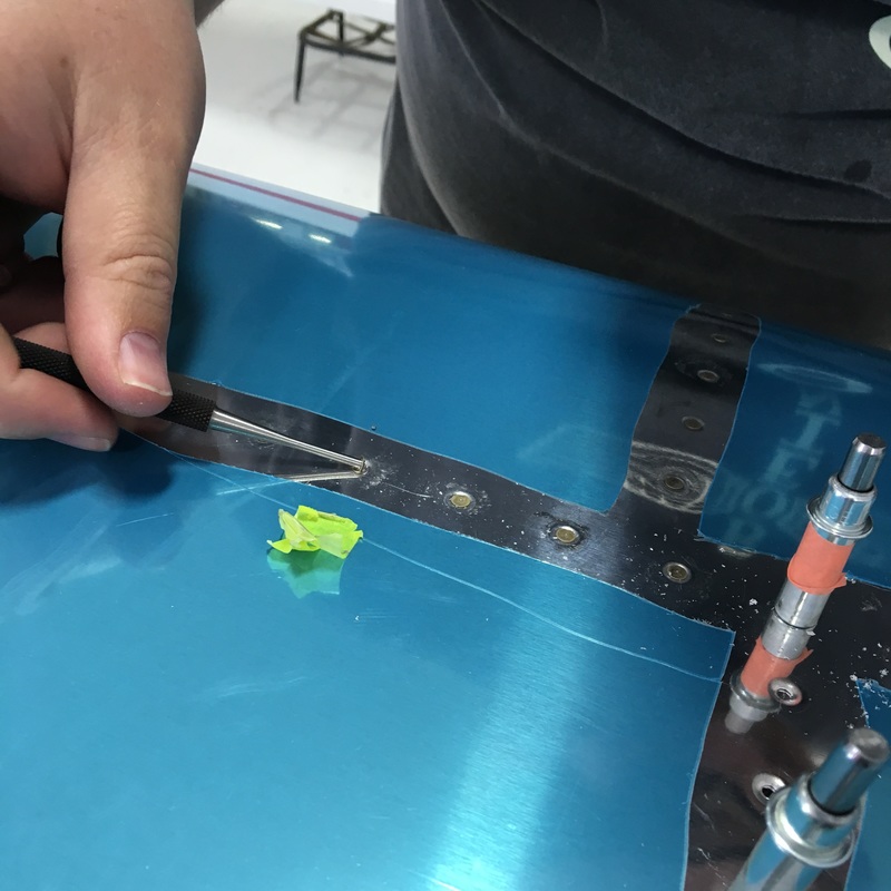
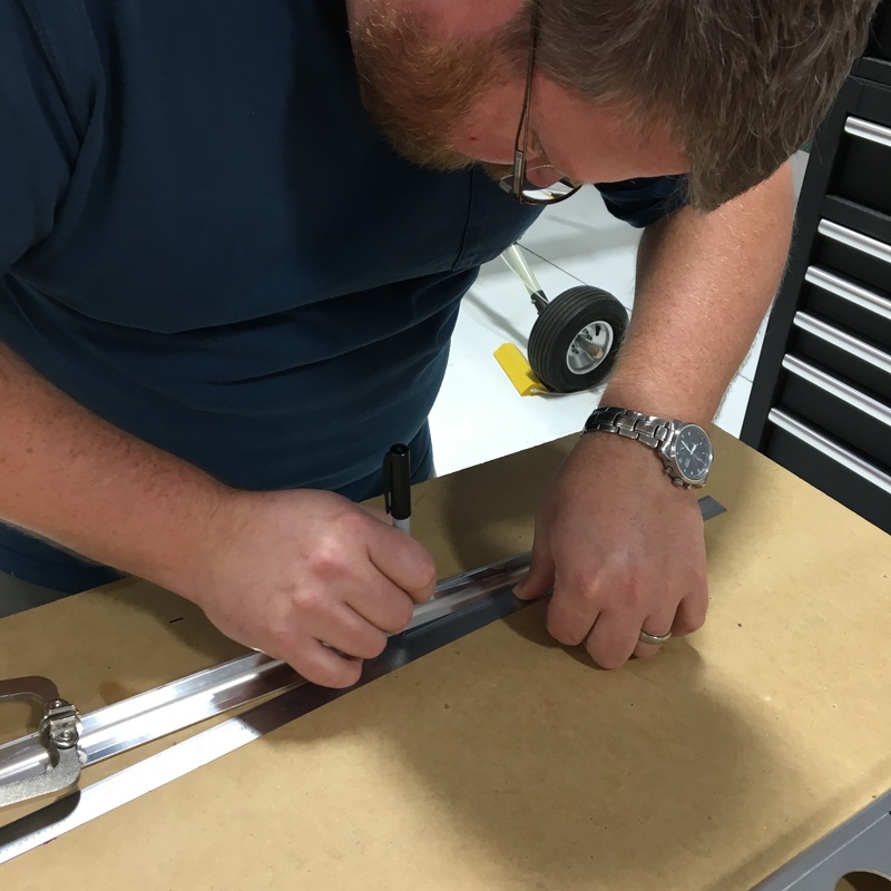
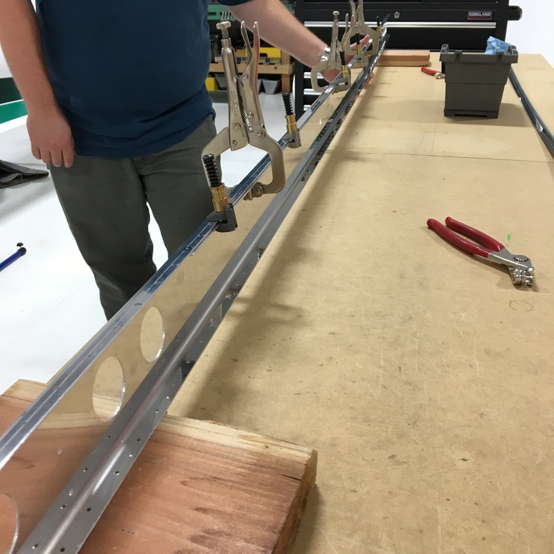
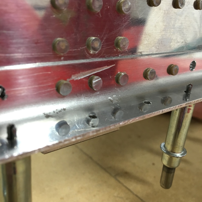
We've officially entered the second year of the build. I think that Mike and I both wish we had made a little more progress over the past year, but it still amazes me to think of everything we've accomplished. Mike also informed me that we've been working on the horizontal stabilizer for 9 months! No wonder it feels like we've been doing this forever. Our work on the plane has been sporadic between the holidays and the winter weather. It's been pretty cold this last month and that hasn't really motivated us to spend time at the hangar. The hangar is heated, but the first 30 minutes up there are pretty chilly. I can wear gloves and a sweathshirt while we work, but my safety gear lives at the hangar is is a chilly 55 degrees when we arrive. I've worked out a system where I put my safety glasses in my pants pocket and wrap my hearing protectors around my bicep. Then they can warm up a little bit while we get set up. We are continuing to refine our workspace at the airport. The biggest challenge we've had to make over the past few months is dealing with dust. A group of middle and high school students are building a Northrop primary glider at the hangar. The whole thing is made out of wood and the sawdust they generate gets on everything. We don't want to seal a bunch of dust into the horizontal stabilizer so we've been covering our workbenches. We started with a cheap plastic drop cloth, but that was quickly filled with holes as (we assume) people pulled back the plastic to check on our work. Once a little hole started, it easily got caught on the hundreds of clecos until the whole things was more hole than plastic. We've graduated to a canvas drop cloth and that has been working better. It also make it look like we're working on something top secret which I kind of enjoy. 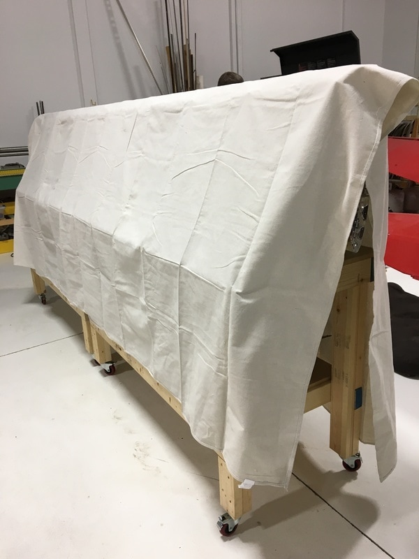 In my last post (over two months ago!) I was complaining about riveting the front spar of the horizontal stabilizer. I estimated that we had about two hours of riveting to go and my estimate was exactly right. We got a roll one day and managed to finish the whole thing in one more session. The remainder of the riveting was uneventful (thank god!) and there was a fair bit of celebrating when we finished. Our next step was to tackle this mess... 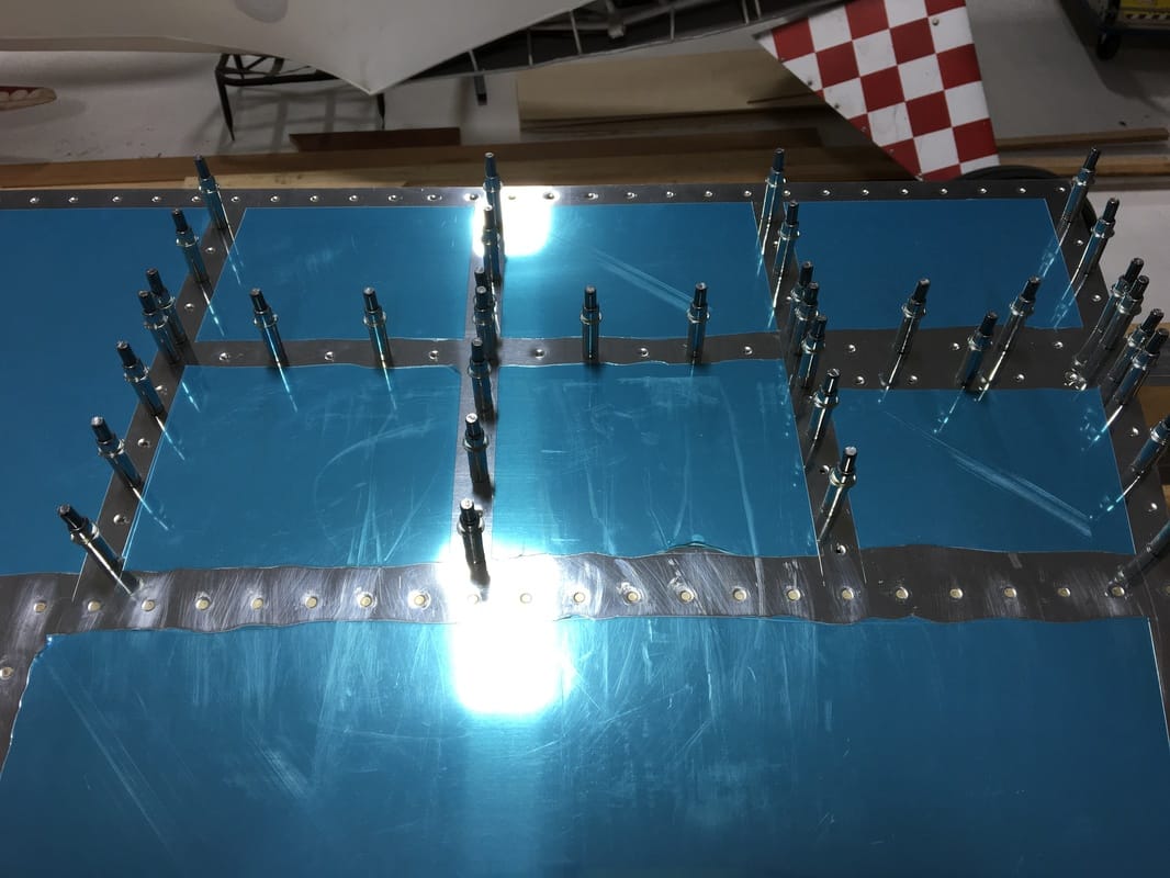 The ribs in this area are interrupted by horizontal stringers that (I assume) reinforce this part of the tail. It's a challenging area to work in because there's not much room for hands and tools in between all those pieces. We started by riveting the lower section of the ribs, below the stringers. The rib that is exposed at the edge was the easiest and we were able to squeeze those rivets. 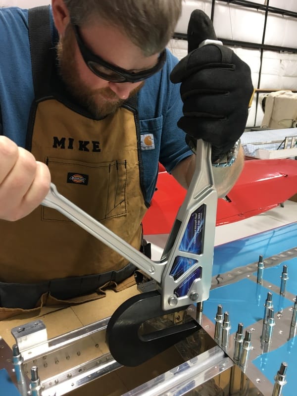 We had to remember to leave a few of the holes open so they can be used for some other purpose down the line. The instructions refer to some sort of horizontal stabilizer fairings. I don't know what a fairing is, but I guess we'll figure it out when we get there. Riveting the ribs behind the stringers was one of the most challenging tasks we've had to do. In addition to the cramped space, I had to be very careful not to damage any of the existing rivets (the rivets that hold the two pieces of the stringer together) with my bucking bar. The stringers also taper at the ends, which caused a problem when my bucking bar slipped. 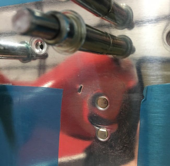 That picture actually make it look much worse than it is...there's not actually a puncture in the skin. We think that at some point my bucking bar bounced and got caught on the very end of the stringer (it's probably only about an 1/8" wide at the very end). Mike was still running the rivet gun and for that second, the rivet gun was hitting the rivet and skin with nothing on the other side. You can see where the rivet below is was bent a little bit on the edge and there's a shallow depression from the gun. The dent (that looks like a puncture) is the very end of the stringer. We decided that we would cause more damage if we tried to fix anything and decided to just let it be. We were more careful after that and didn't have any more mishaps. Our next step was to rivet the stringers to the skin. The stringers are made from two "L" shaped pieces that are riveted together to make "T" shape. There is a row of rivets that runs down each side of the cross stroke that make up the top of the "T". The main stem of the "T" blocks your view of one side. Here, maybe some pictures will help explain this better... 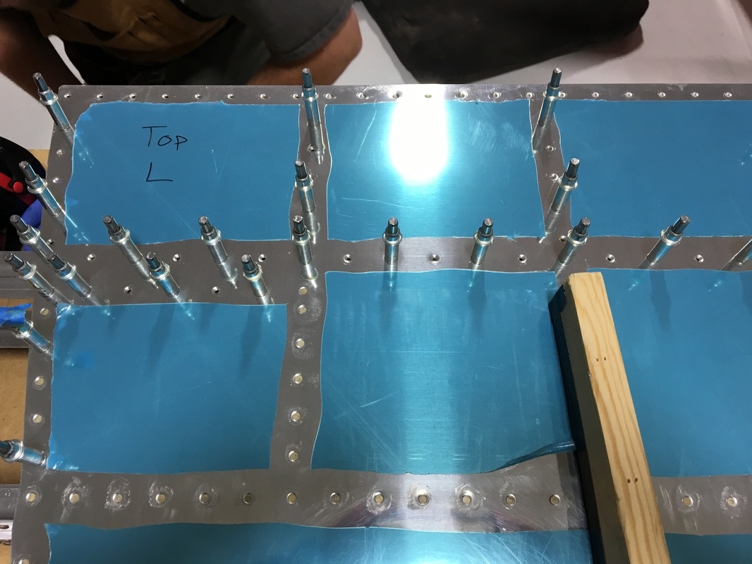 On the left, you can see that there is a double row of horizontal rivets that run between the first and second rib. 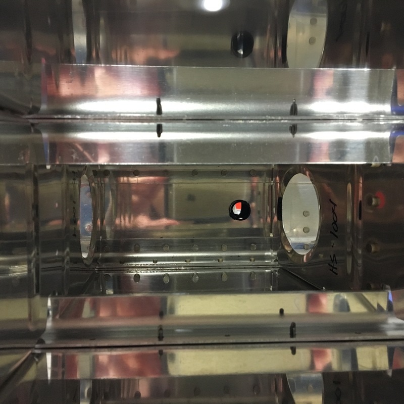 When you look inside, you can only see one row of clecos because the others are hidden on the other side of the stringer. How do you rivet something that you can't see and can't reach? You use a special bucking bar! 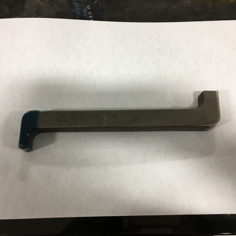 That 90 degree angle at the end lets you reach the far side of the stringer, like so... 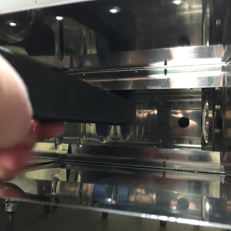 I don't even have to stick my entire arm inside! It was some of the easiest riveting we've done on the whole plane and this is where I had a major plane building epiphany. A heavier bucking bar makes all the difference! I've almost exclusively been using our small tungsten bucking bar and while it's dense, it's too small to be very heavy. That means it bounces all over the place while we are riveting. The angled bucking bar I used for the stringers is made out of steel and that thing barely moves when we rivet. You don't want to drop it on your toe, but the decreased movement means my hands don't take such a beating as they get bounced around. It has also increased my confidence because I'm able to hold the bar in place more easily. That didn't stop me from completely mangling a rivet, but it's the only one that I've messed up in several weeks. Mike made me take a picture of it because it truly was a magnificent mistake. 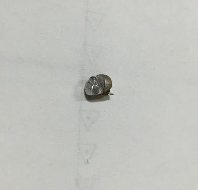 Next, we'll finish riveting the ribs to the skin. I counted, and that will take another 140 rivets, easily 2 or 3 work sessions.
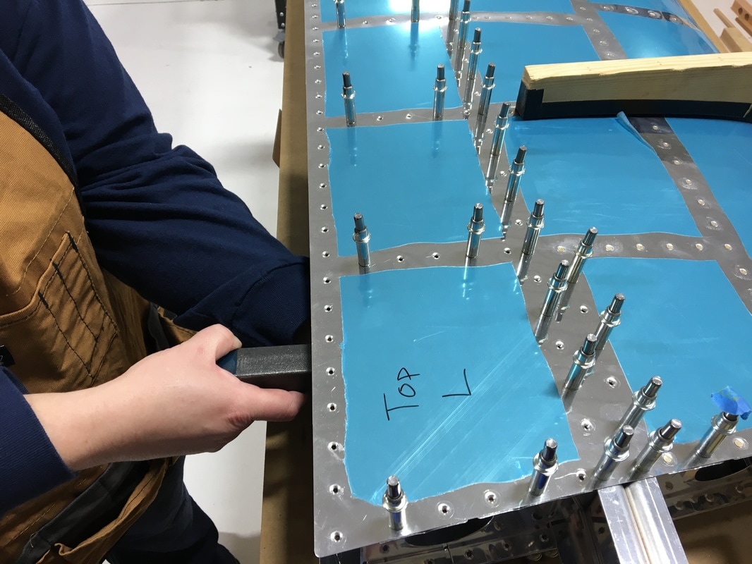
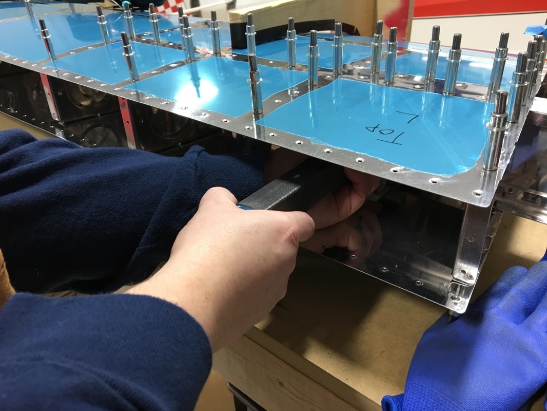
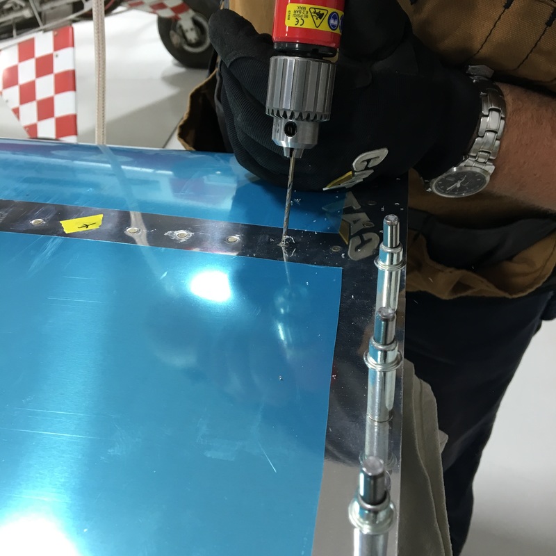
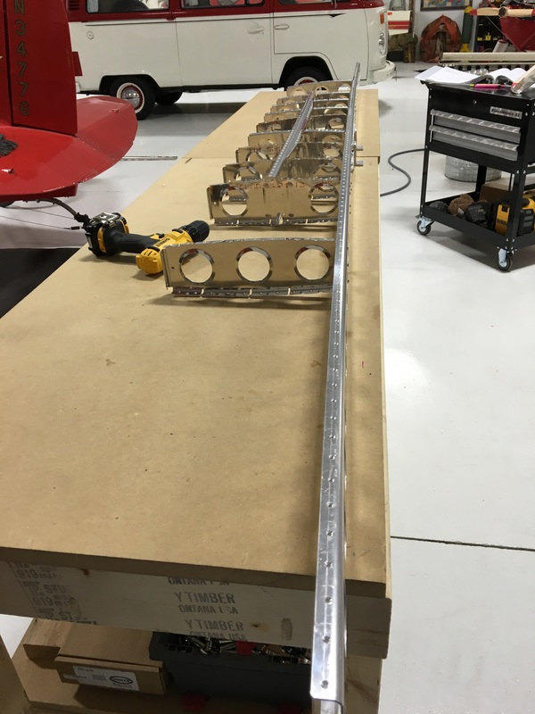
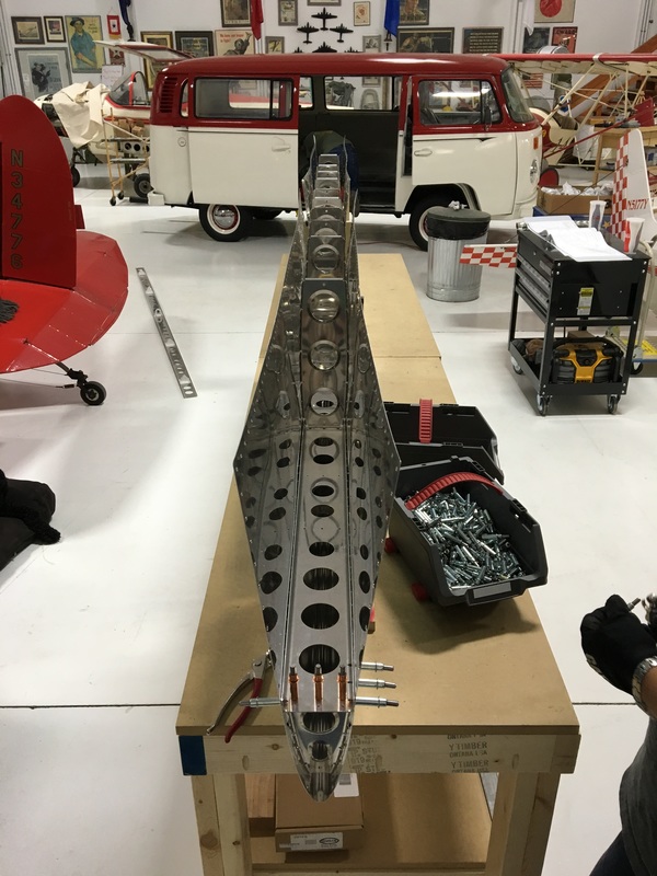
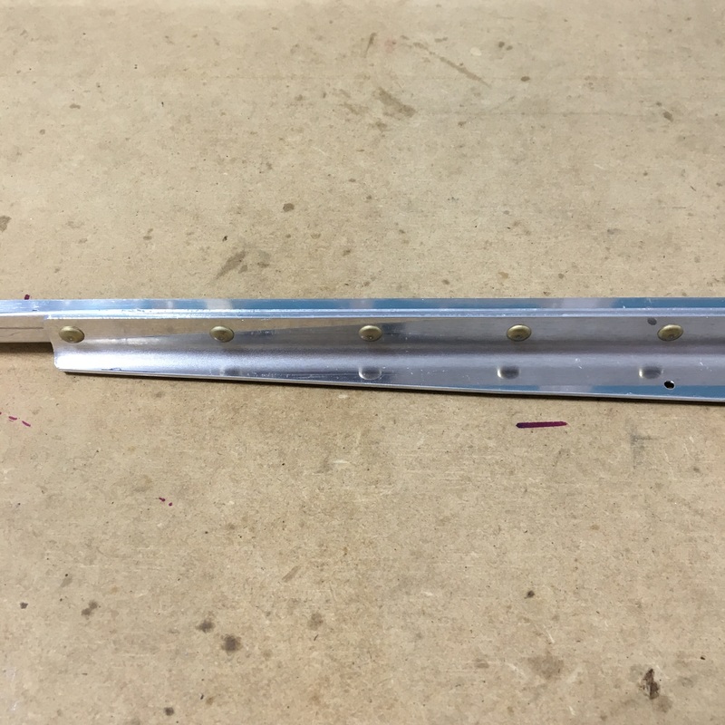
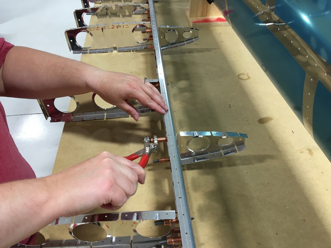
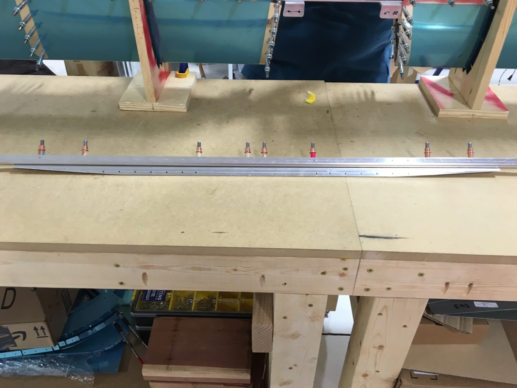
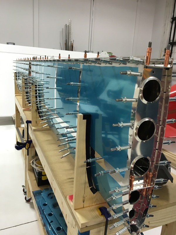
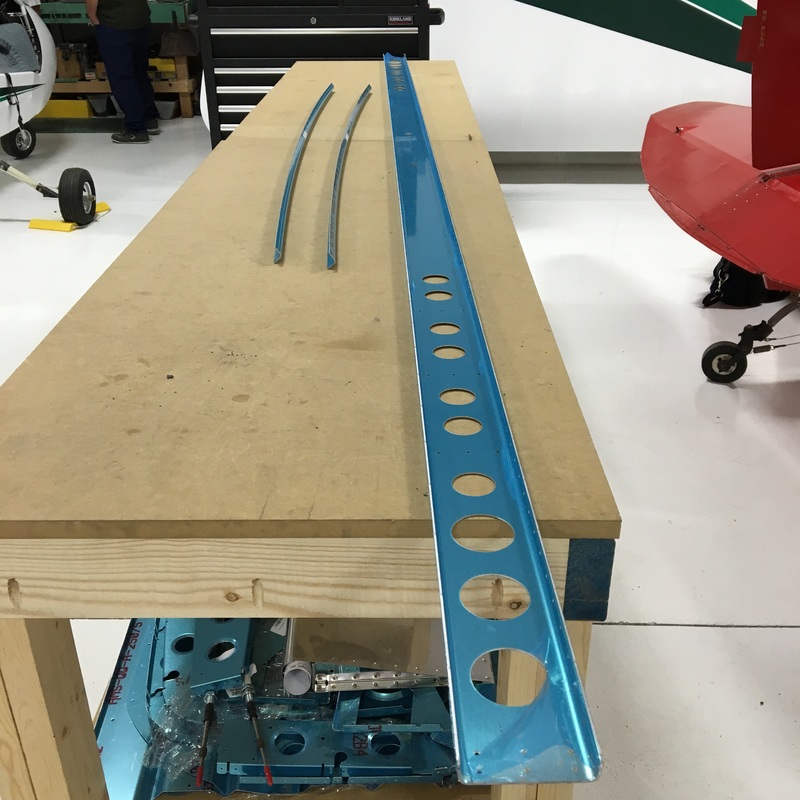
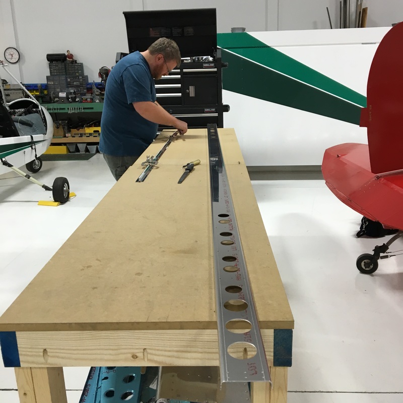
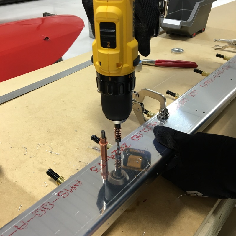
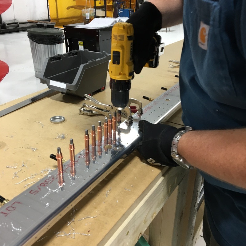
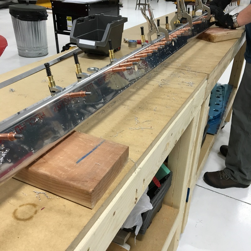
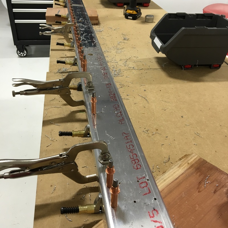
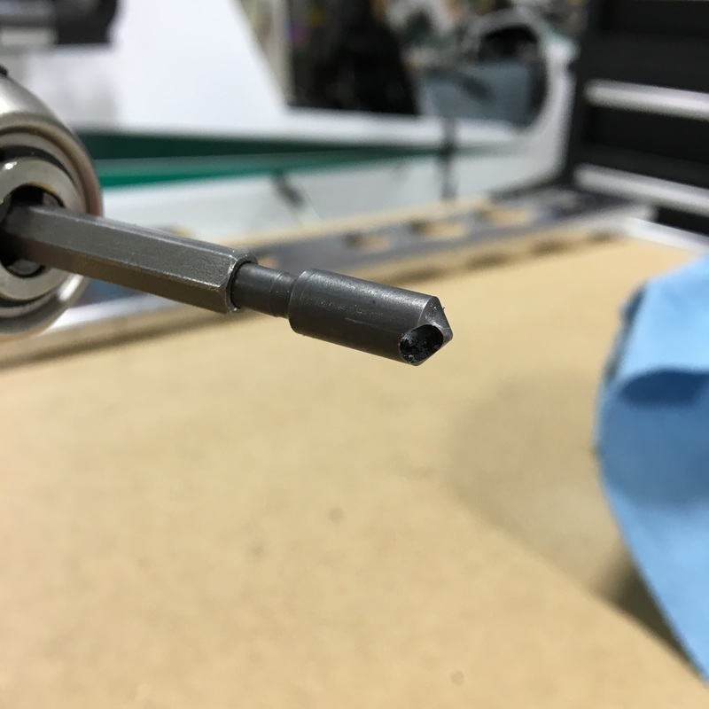
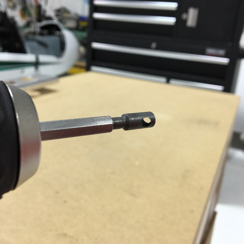
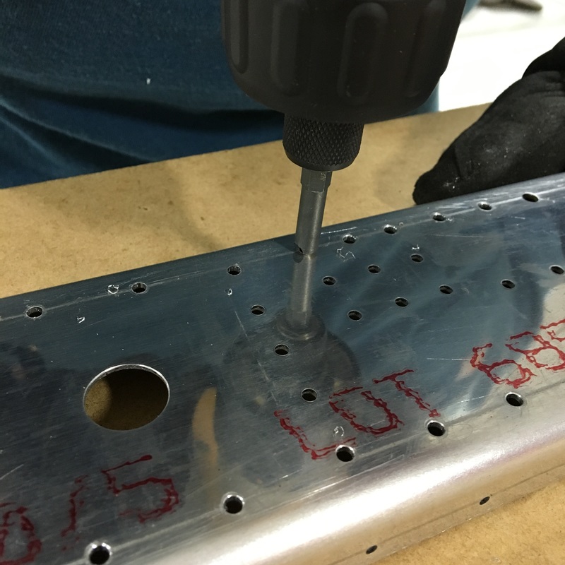
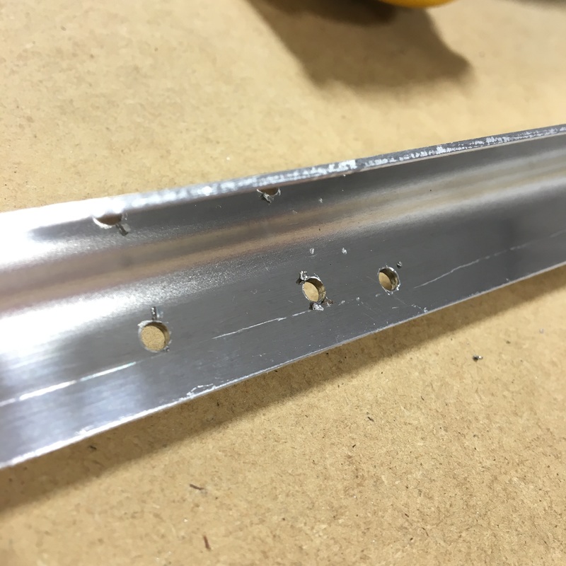
I know, I know, it's been a long time since I've posted any updates. What can I say, things have been pretty hectic around here and we haven't had much time for the airplane lately. I promise that we have been making some progress over the last six weeks so let's get caught up. After we finished pop riveting the front spar into place, our next task has been to rivet the skin to the front spar. This has been my least favorite part of the build so far. By the time I'm done, you'll probably understand why, but one of the main reasons it has been so miserable is the sheer number of rivets. The front spar is over 11 feet long and there is approximately one rivet per inch...on each side. 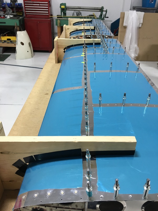 See that line of clecos that runs down the center of the picture? That represents every other hole that needs a rivet. I haven't counted how many rivets there are on each side of the spar, but it's more than a hundred. Before we started riveting, we color-coded our diagram and clecos to make sure we use the right size rivets in the right holes. Every rivet is the same diameter but the length varies based on the number of metal pieces we are riveting through. 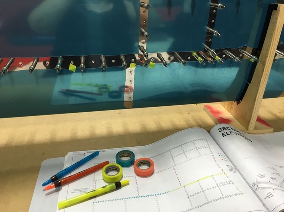 We didn't put tape on every cleco this time, just the first and last cleco in a particular length. Even using this modified method, it took at least half an hour to complete. Once everything was marked, we were ready to start riveting. This is where we discovered the other reason I hate this step. Once everything is clecoed together, the horizontal stabilizer is really narrow. Here's a picture to demonstrate. 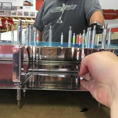 I can barely fit my hand inside the horizontal stab...and I have ridiculously small hands to begin with. You can also see that there are ribs every 8 to 10 inches that you have to work around. There are even several areas where the extra stringers make the space even narrower. I can fit about three and a half fingers between the stringers and in these places I have to insert my hand horizontally and then rotate my arm. 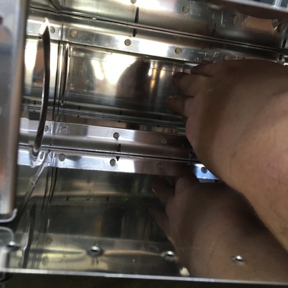 Before we move on, can we all just take a moment to appreciate how horrible that last picture was. My hand looks seriously deformed and I have no idea where my wrist disappeared to. The number of rivets and cramped space make this section a real bummer to work on. It also didn't help that one particular day was our least successful day of riveting so far on the project. I believe that we installed about 10 rivets that day and I messed up 3 of them with the bucking bar. It was the most frustrating experience, I just couldn't seem to hold the bucking bar still and it would slip off the edge of the rivet leaving a giant gouge. 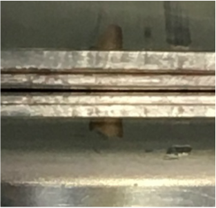 Things went so badly that we gave up on riveting after about 20 minutes and that seriously damaged my confidence. I agonized over why I just couldn't seem to hold that bucking bar still and even accused Mike of changing the setting on the rivet gun so it would be super powerful. I realized several hours later, when I tried to squeeze a water bottle, that the real problem was that my hand and arm muscles were super tired from washing walls the day before. If I could barely squeeze a water bottle, how could I possibly hold a bucking bar in place? Lesson learned (and I apologized to Mike for blaming him). We still had to replace the bad rivets, which meant drilling them out first. That meant that Mike got to use a new tool he had ordered just for this purpose. 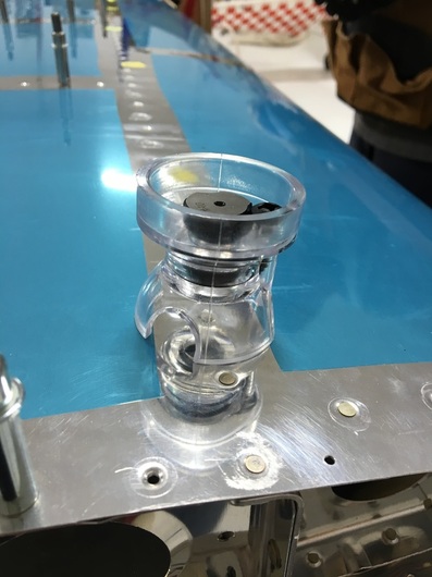 This little doodad helps keep that drill bit perpendicular to the skin and also gives you something to hold onto while you drill. We had some trouble getting the hole centered so Mike ended up drilling the last bit by hand. No matter how careful you are, you usually end up enlarging the hole slightly when you remove a rivet. Because there are so many layers of metal at this point, and some of those layers are countersunk or dimpled, we used a special kind of rivet to replace the ones we removed. They are, I'm not kidding you, called oops rivets. 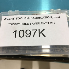 The head of an oops rivet is basically the same size, but the shaft is one size larger. Here's a picture to demonstrate. 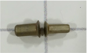 This lets us drill out the holes to a larger size without worrying about the countersinks and dimples. Once the oops rivet is in place, you honestly can't tell the difference. 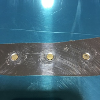 Once we replaced all the messed up rivets we were able to continued working our way day the spar. It took me a couple of work sessions to regain my confidence with using the bucking bar but everything has been okay since. It's still not a very fun section to work on (even Mike agrees with me on that) but we are making progress. We have completed about six hours of riveting and we estimate about another two hours before we are finished. That will be a happy day!
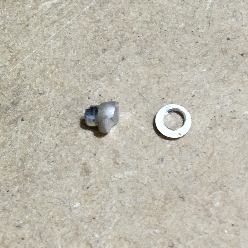
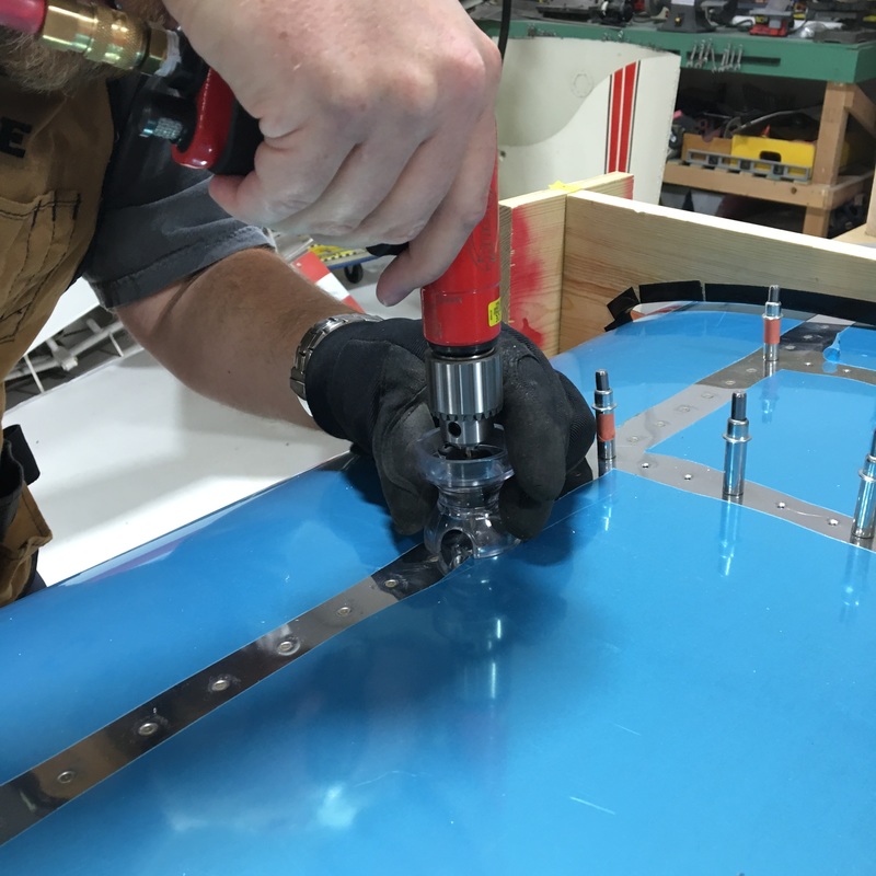
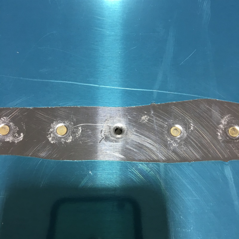
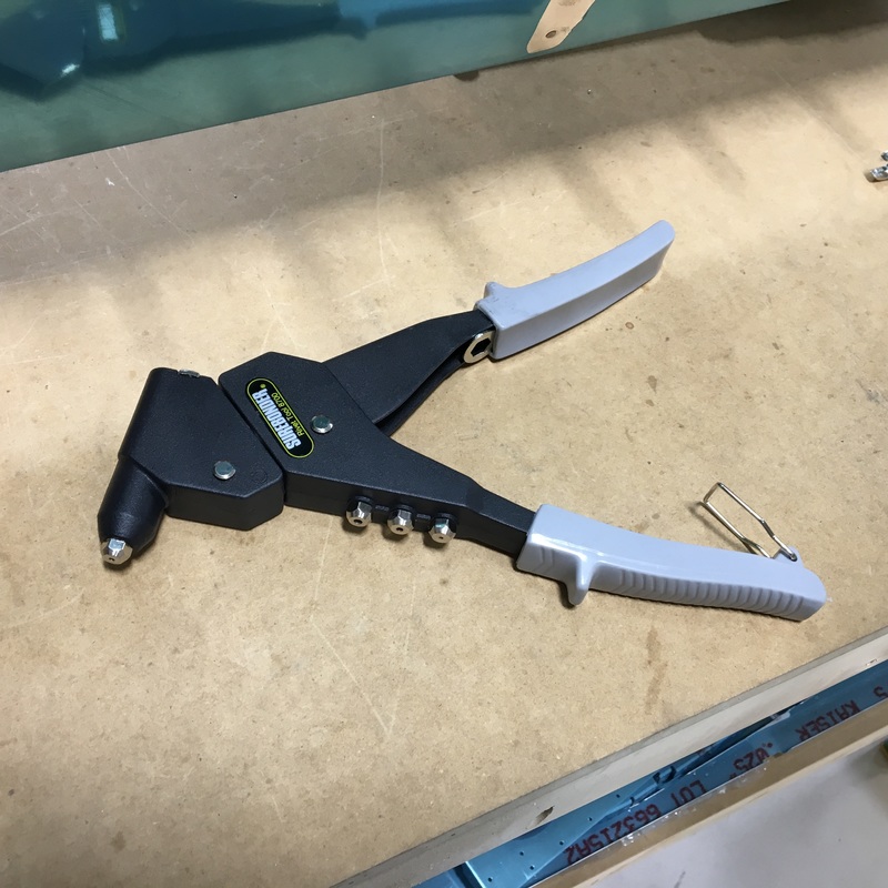
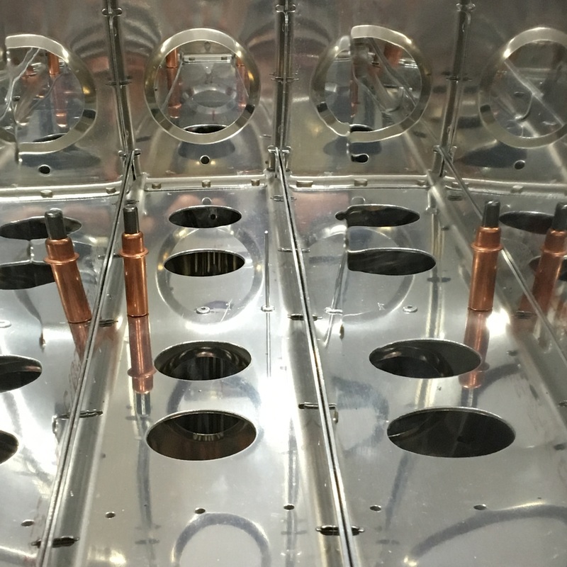
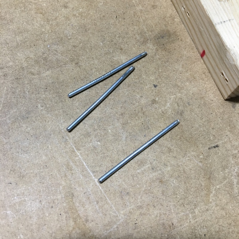
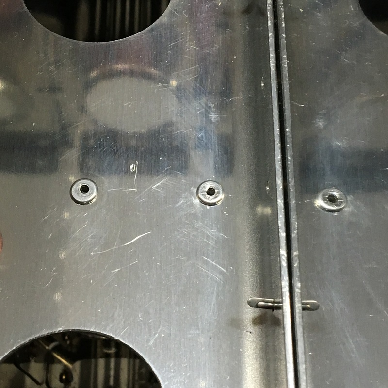
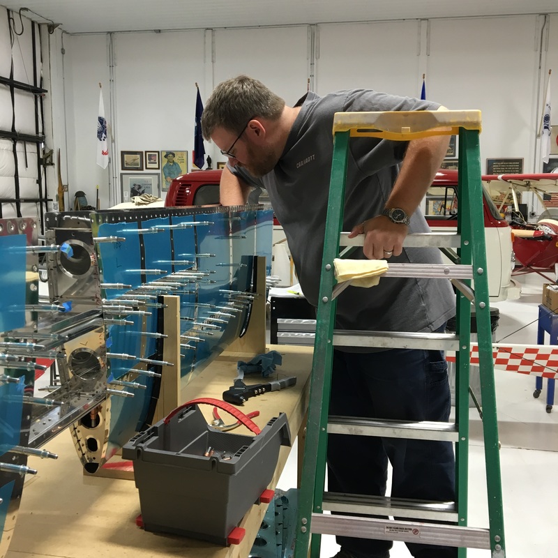
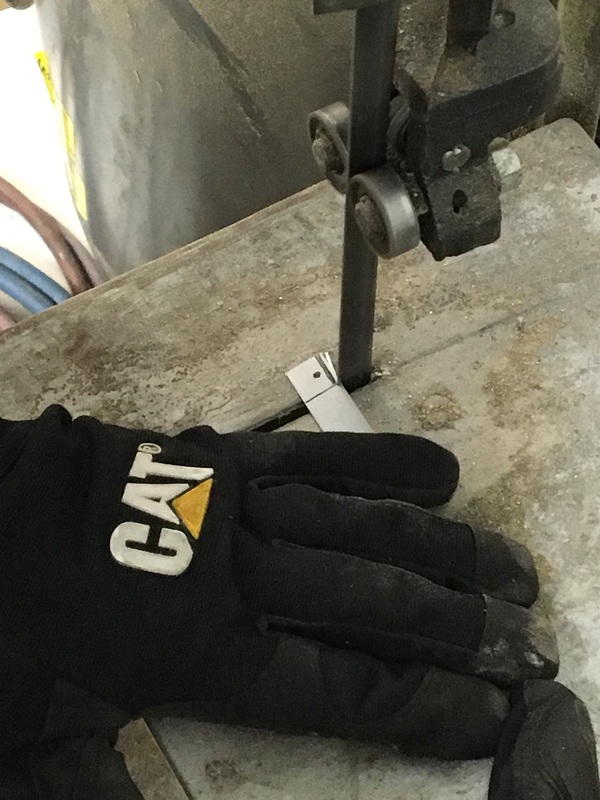
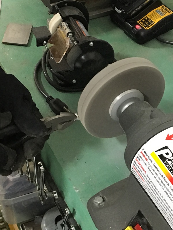
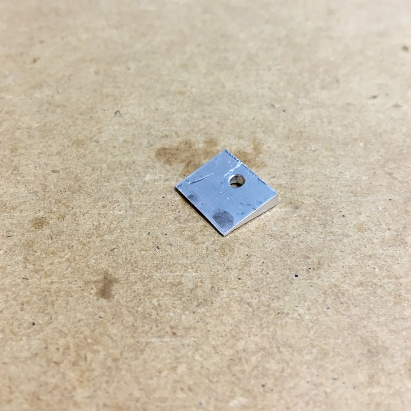
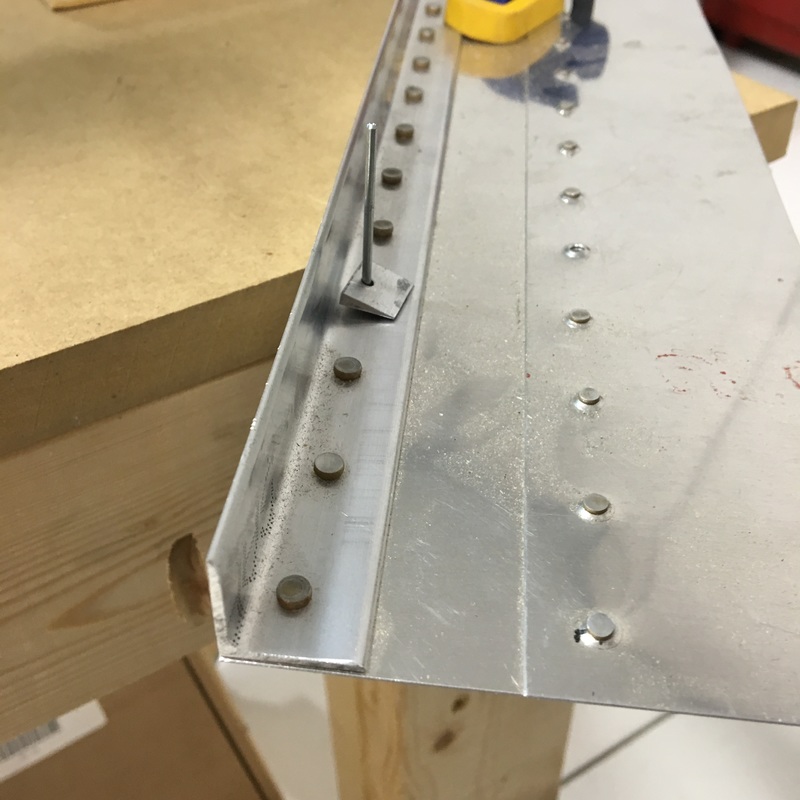
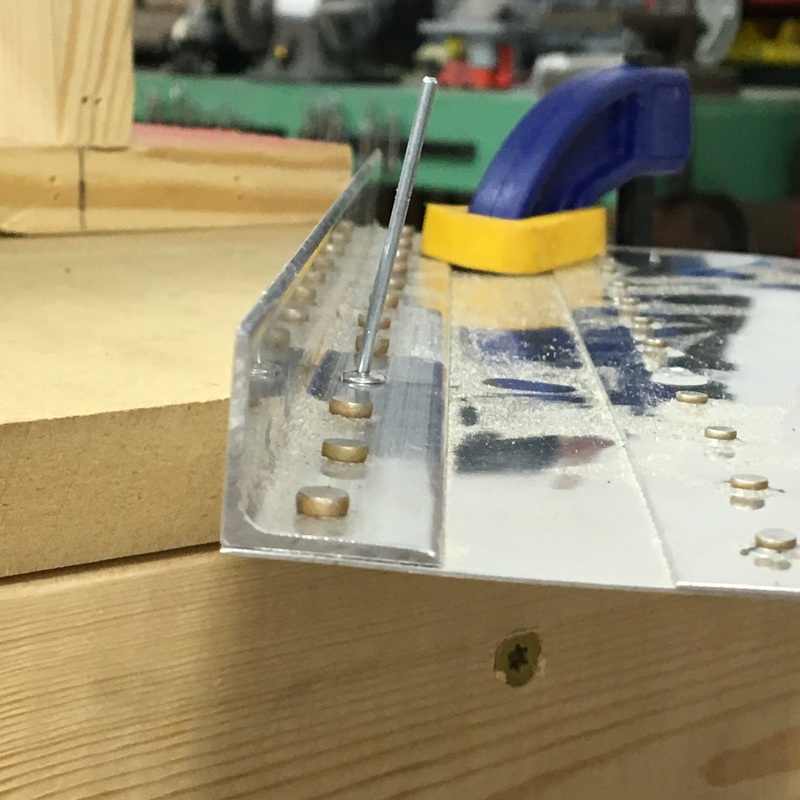
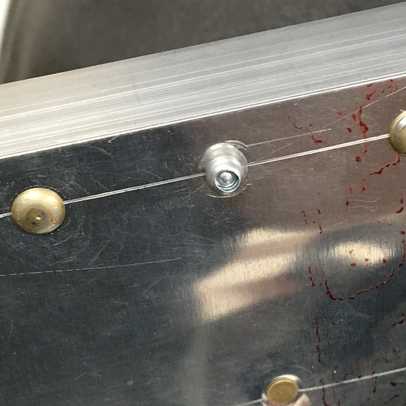
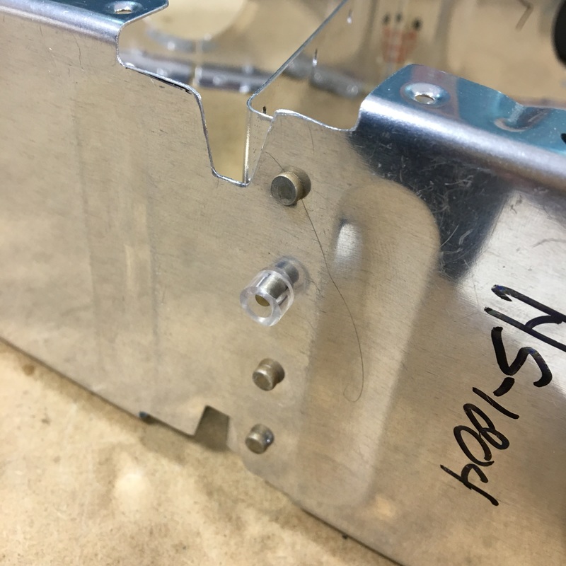
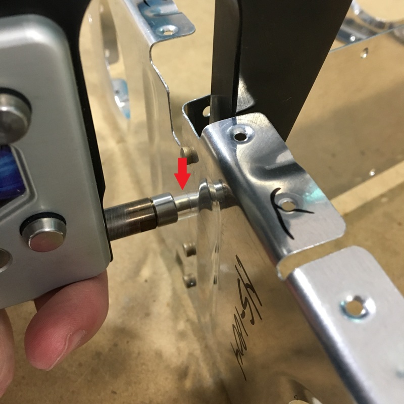
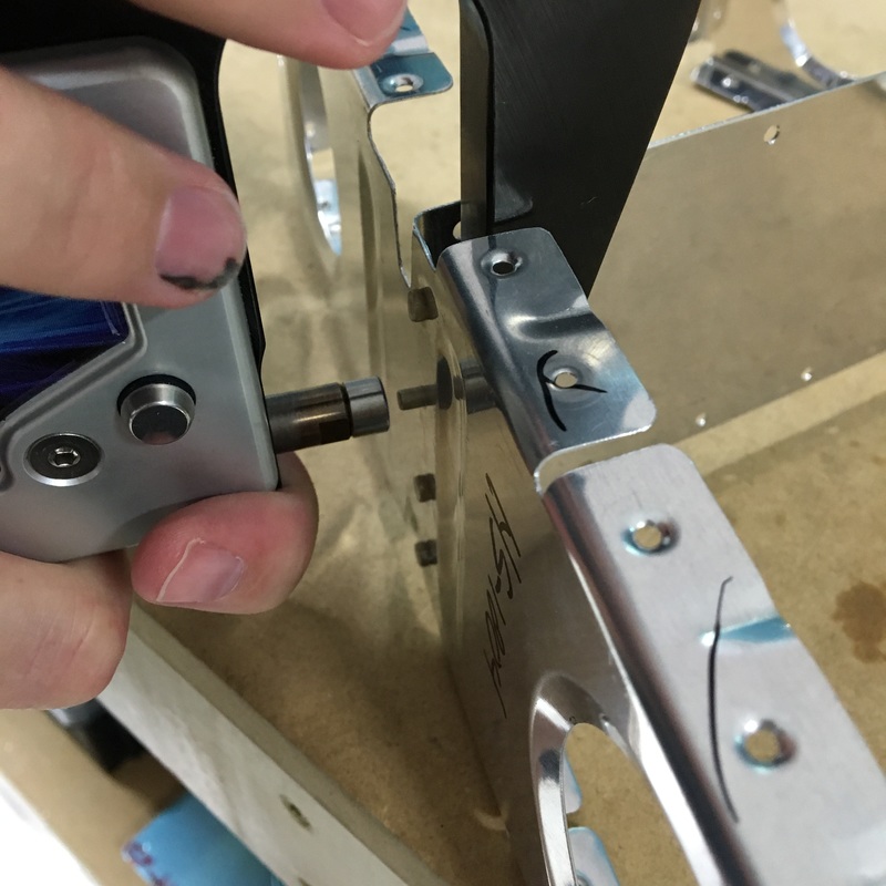
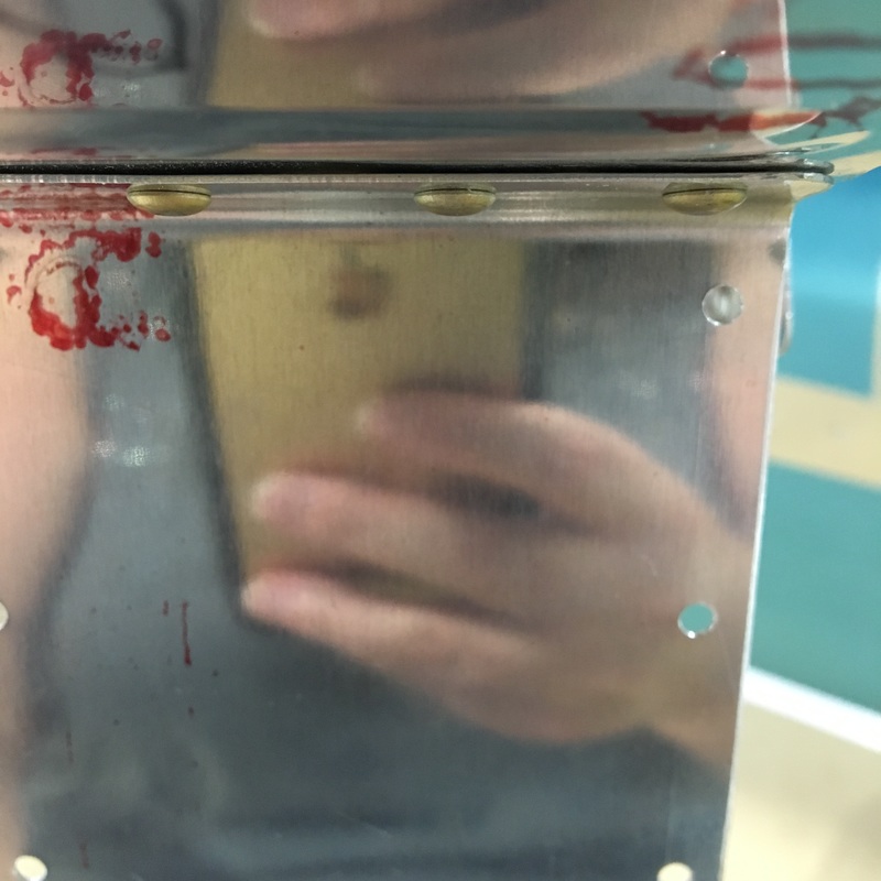
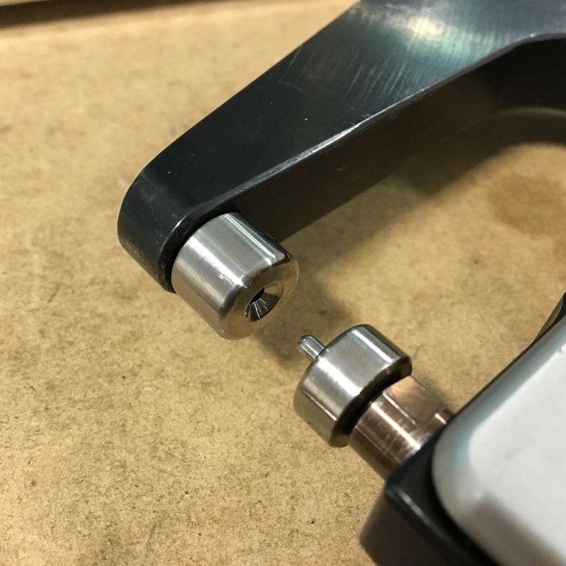
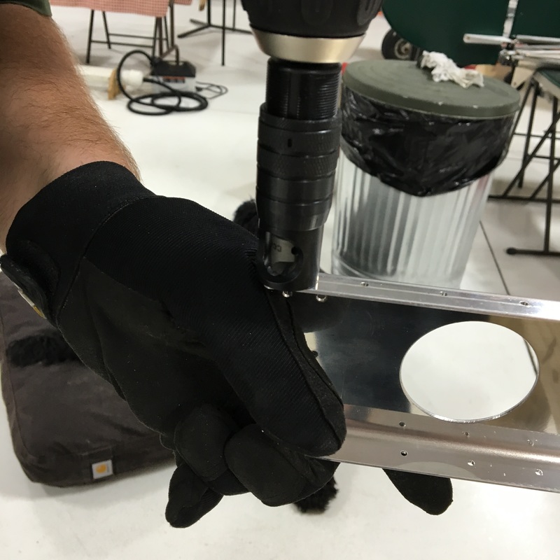
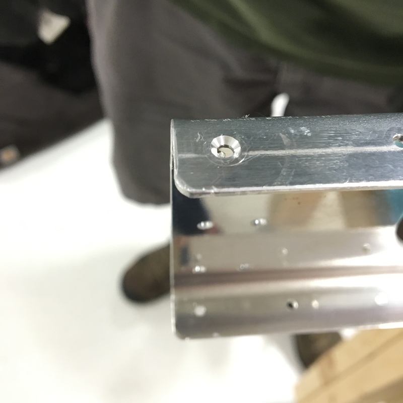
Now that the front spar is in place (with correctly sized countersinks) we have to attach it to the nose ribs we previously riveted into place. The problem is that once the spar is in place, the front of the horizontal stabilizer is completely closed off and inaccessible. We need to put rivets in to replace those copper colored clecos, but we can't squeeze or buck most of the rivets because we can't reach both sides. 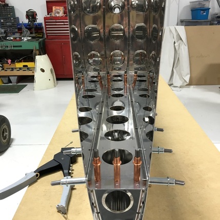 Instead, we will use pop rivets (also known as blind rivets or pull rivets) to attach the spar to the nose ribs. Pop rivets look like this. 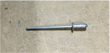 The fat end (on the right) is the portion of the rivet that will actually hold everything together. The long pin (on the left) breaks away once the rivet is in place. To use a pop rivet, you need a special tool (surprising, I know!). The wide end of the rivet is placed into the hole and the pin goes into the pop riveter. When the handles of the riveter are squeeze together, it compresses the rivet and breaks off the pin. Mike had to stand on a ladder to reach most of the rivets. Many of the holes needed to be reamed before we could install the rivets. We tried to use the regular hand drill with the angle drill attachment but there wasn't enough room. I couldn't get a decent picture of Mike trying to use the drill (darn my short stature) so I held the drill while Mike stood on the ladder and took a the picture. 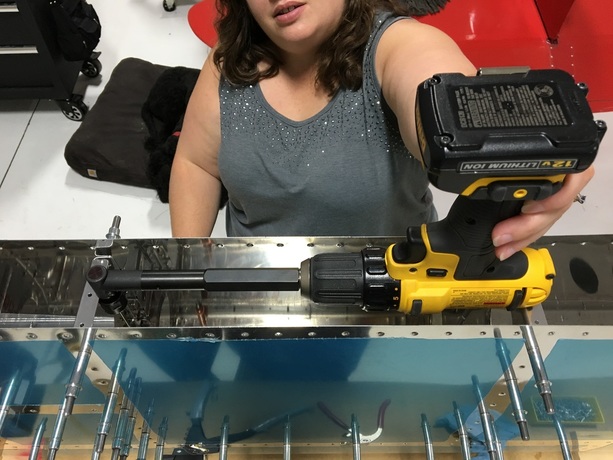 The air drill is quite a bit smaller, and was able to reach most of the holes without using the angle attachment. Installing all the rivets seemed liked a pretty straight forward job, but we did run into a few snags. Our first problem was due to poor decision making but was, thankfully, in an area that was easy to access. At the end of each spar, we were able to use regular rivets the rivet gun. I can't even remember exactly what happened here, but the rivet on the right obviously isn't seated properly. That gap between the head of the rivet and the spar is a bad thing. 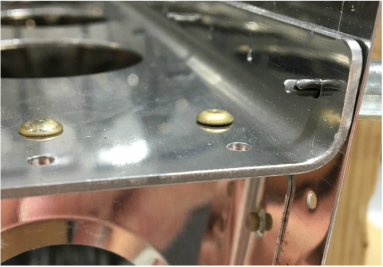 We had to remove the rivet and try again, but during that process the flange on the nose rib got bent. The obvious solution was to use a clamp to hold the spar and the flange together while we placed the rivet. The problem was that the clamp had to practically cover the rivet hole before the pieces were in the correct position. We decided to try the rubber hose trick that we used earlier, but this time with the bucking bar. 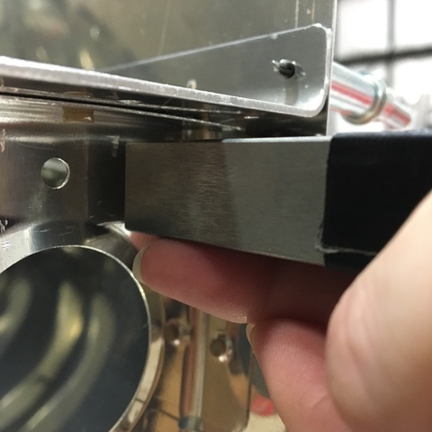 You can just barely see the tiny sliver of rubber hose between my bucking bar and the bent flange. The process worked fine, but as I look back on this whole process I have to wonder why were weren't using the squeeze riveter in the first place. Were we trying to make our lives harder? The second challenge we encountered was installing pop rivets when there wasn't enough physical space for the pop riveter. When the nose ribs and inspar ribs lined up, there was only about a quart of an inch between the pin of the rivet and the rib. There's no way the pop riveter is going to fit in there! 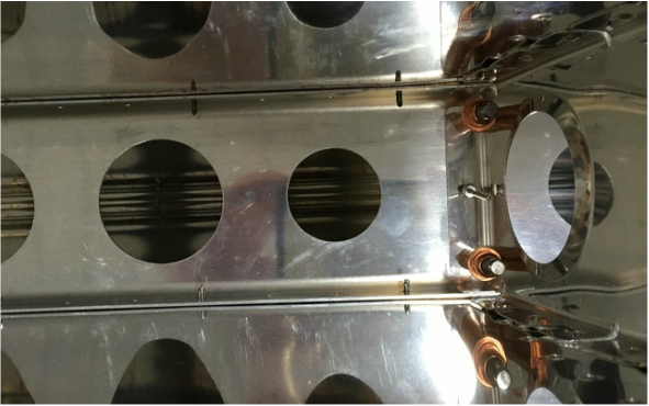 So...Mike fabricated a widget (the actual, technical term according to Mike) so we could get those rivets in place. The widget is really just a very tiny wedge with a hole drilled in the middle. 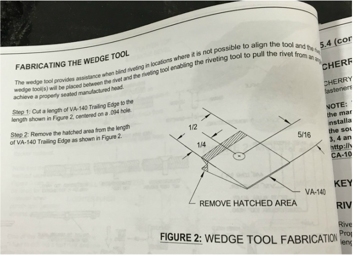 I'd like to point out that the whole wedge is only 1/2 inch wide. To make the wedge, you use trailing edge - a thin, wedge shaped piece of aluminum that we will be using elsewhere on the plane (I'm not going to say where we will be using it, because I honestly don't know at this point). Mike drilled, cut, and ground until we ended up with a beautiful, tiny wedge. The wedge allows us to use the pop riveter at an angle but still set the rivets in place correctly. The instruction manual has a nice set of diagrams that describe how it works. 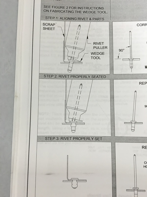 We were both a bit skeptical that the wedge was going to work, so we decided to test it on some scrap material first. We stopped half way through to make sure that the head of the rivet was flush and you can clearly see (bottom left) that the pin has been pulled at an angle (thanks to the wedge) but the head is properly seated against the metal. You can also wee what the shop head looks like in the bottom right picture. After our test, we were able to finish the rest of the pop rivets in a matter of minutes.
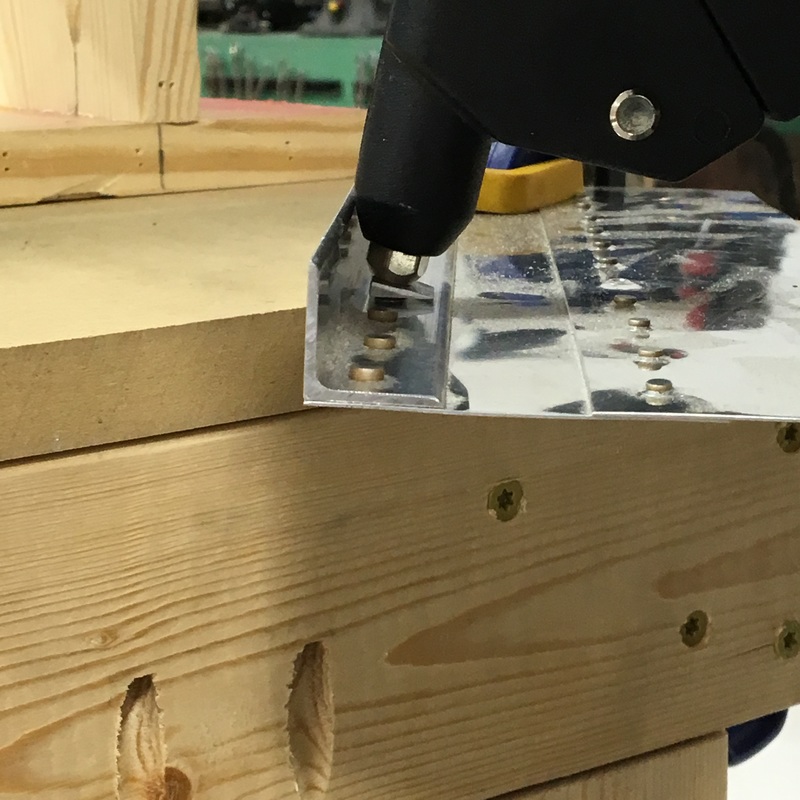
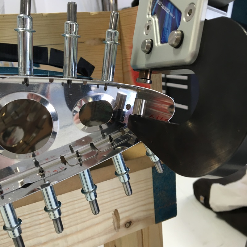
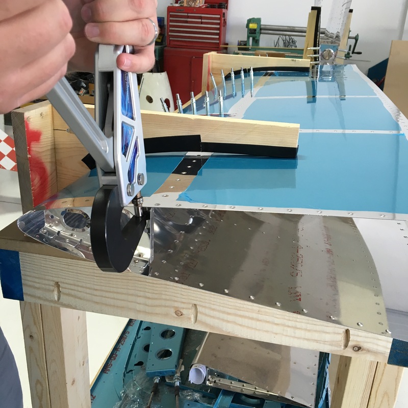
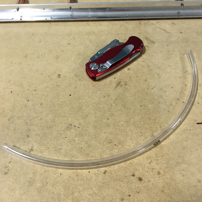
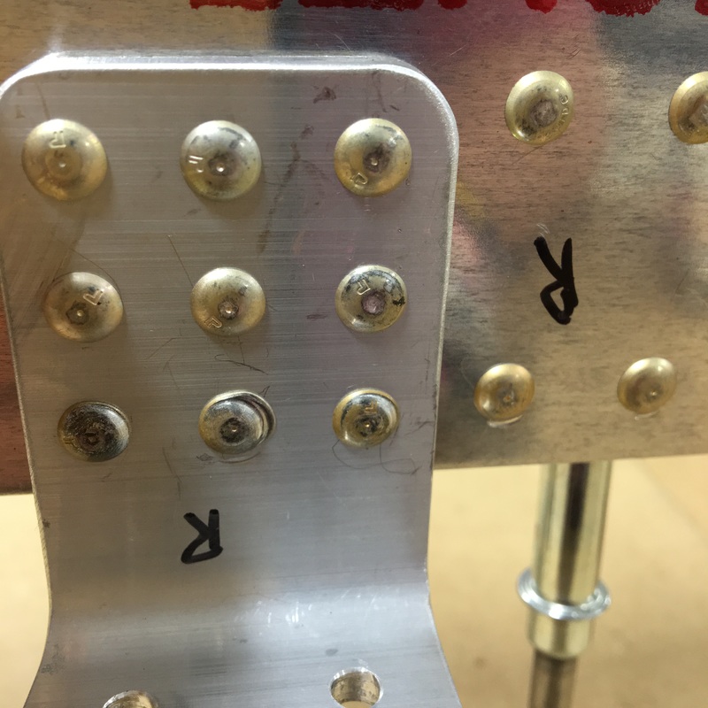
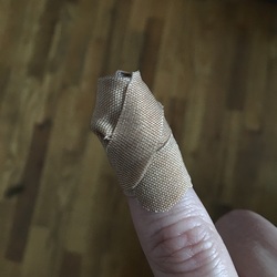 After a week off due to a tragic cheese grater incident, we are back to work and ready to rivet. It was surprisingly hard to convince Mike that I couldn't hold a bucking bar without using my right index finger. In retrospect, we could have kept working because I had to buck half the rivets with my left hand (don't tell Mike I said that) but it was also nice to have a little time off from the build. We are continuing the final assembly process for the horizontal stabilizer and I'm very excited to report that we only have three pages left in this section of the construction manual. It may take us a couple of months to finish those three pages, but it feels like we can see the finish line. After the challenges we had last week while riveting the skeleton structure together, I was a little nervous that we were working with the skins this week. Our first task was to rivet the nose ribs into the skins. 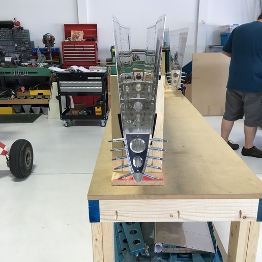 There are four nose ribs on each side of the horizontal stabilizer. The two ribs on each end are obviously very accessible so we used the rivet squeezer on those. The most challenging part was dealing with the odd angles of each rivet. I would line up the squeezer so it was square with the rivet and monitor everything while Mike provided the muscle. The interior ribs were quite a bit more challenging. There's no way the rivet squeezer could possibly reach so we had to use the rivet gun and bucking bar. As usual, Mike ran the gun while I handled the bucking bar. The front crease of the horizontal stab is quite small and it was really hard to get the bucking bar into that small space. I also didn't have a good line of sight to see if the bucking bar was square to the rivet. The rivets closest to the front crease were hardest because the angle is pretty sharp and I barely had enough room by my hand and our smallest bucking bar. We managed pretty well by setting those rivets in small increments. Mike would give the rivet a short series of taps with the gun and then I would peek at our work and adjust the bucking bar as needed to make sure we were getting a nice even shop head. Another challenge was dealing with the reflections caused by the shiny surface of the skin. I've shown you pictures where the inside of the stabilizers looks like a kaleidoscope... 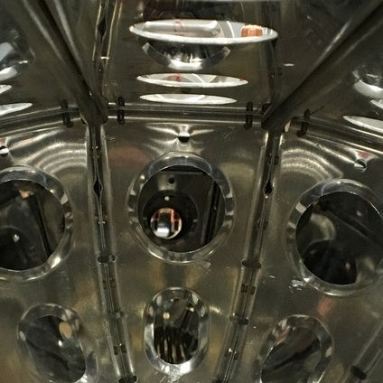 It was very hard to get a good look at each rivet to tell if everything was square or if I needed to adjust the bucking bar. In the end, I think we did a pretty great job and I think we were both happy that we didn't have even any minor catastrophes. Once we had the nose ribs riveted in place, it was time to add the front spar and attached ribs. We clecoed the front spar assembly to the nose ribs (the copper clecos in the picture on the right) and to the skin (the silver clecos). Once we got everything put together, we were ready to rivet the spar assembly into place...or so we thought. Before we started riveting (luckily) Mike noticed that the skin was not sitting flush against the spar. It turned out that none of the countersinks we had put into the spar were deep enough to accept the dimples on the skin. So, we took everything apart so Mike could redrill all of the countersinks. 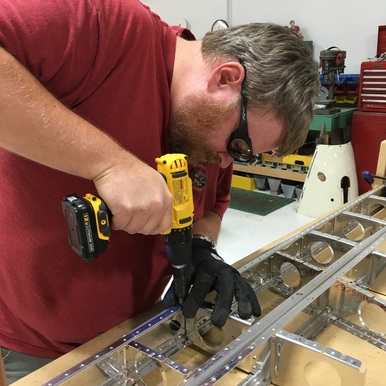 Then, we put the whole thing back together and clecoed everything into place...only to realize that while Mike had enlarged the countersinks on the spar, he hadn't enlarged the countersinks on the stringers. So, we took the whole thing apart again, so he could redrill those countersinks. 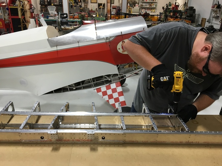 While Mike redrilled holes, I read my book and Zoey provided emotional support. 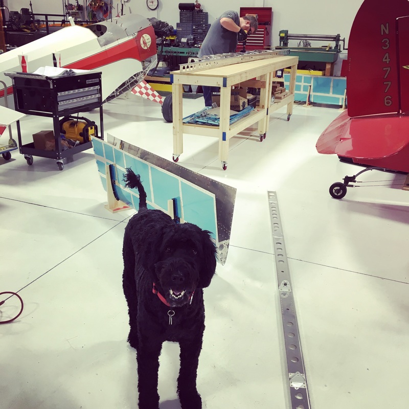 Finally, we were able to put everything together for the third (and hopefully final) time. 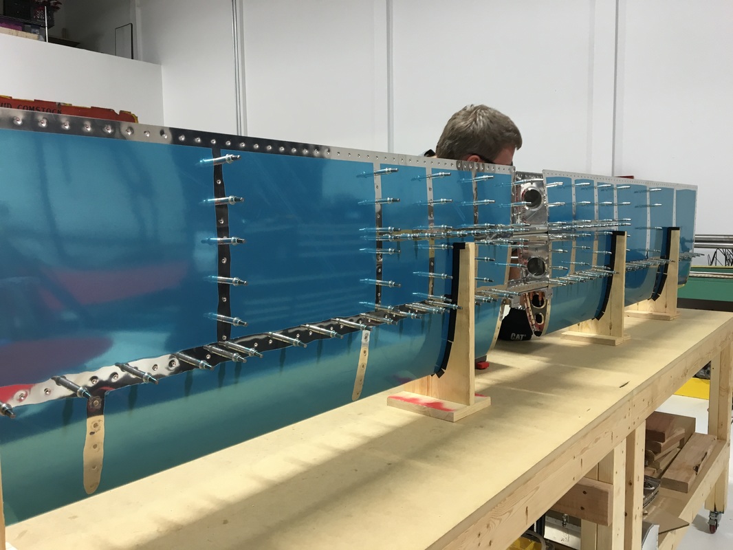 We've started riveting the horizontal stabilizer! What a wonderful feeling to be done with all the prep work on this part of the plane. I don't know that I could have faced drilling, deburring, and dimpling another hole. Finally getting to permanently attach pieces if both very exciting and very nerve wracking. We haven't done much riveting lately and let's just say that those skills were a little rusty. Things started out smoothly enough as we put together our first pieces of the skeleton. 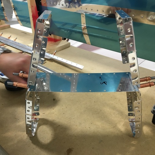 When we rivet small pieces like this, there are often visible gaps between the flange of one piece and the web of the other. As we started riveting these pieces, we noticed the gaps and, while they aren't necessarily a problem, Mike wanted to test out a new technique he had read about online. Mike cut a very small piece of clear rubber tubing just slightly longer than the rivet shaft. The theory is that the rivet squeeze first applies pressure to the rubber tube, helping to cinch everything together before you actually begin squeezing the rivet. I was kind of skeptical that there would be much change, but there was a small but noticeable difference when we compared the two sides. Next we riveted the stringers together and attached them to the skeleton assembly. We used the squeeze riveter as much as possible but had to buck a few rivets that we just couldn't reach. Our skills with the rivet gun and bucking bar were really rusty and some of our work wasn't very good. 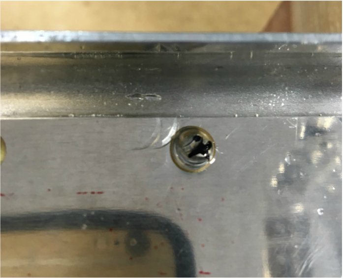 You can see the parentheses where the head of the rivet gun hit the rivet head and the metal next to it. This usually happens when the bucking bar slips and the whole thing moves before Mike can stop the rivet gun. The black "x" shows that Mike marked it for replacement. He used the rivet remover bit for the drill to take out the damaged rivet so we could try again. I still haven't gotten over my anxiety with drilling out rivets (you may remember the trouble we had the first time we drilled out a rivet and the broken drill bit caused so much damage). Everything went smoothly this time but it is still stressful for me. Part of our problem was that everything was very wobbly at this point and I was trying to simultaneously hold the bucking bar and keep the skeleton still. We figured out a way to secure the pieces to the workbench so we could focus on riveting rather than on keeping the pieces steady. 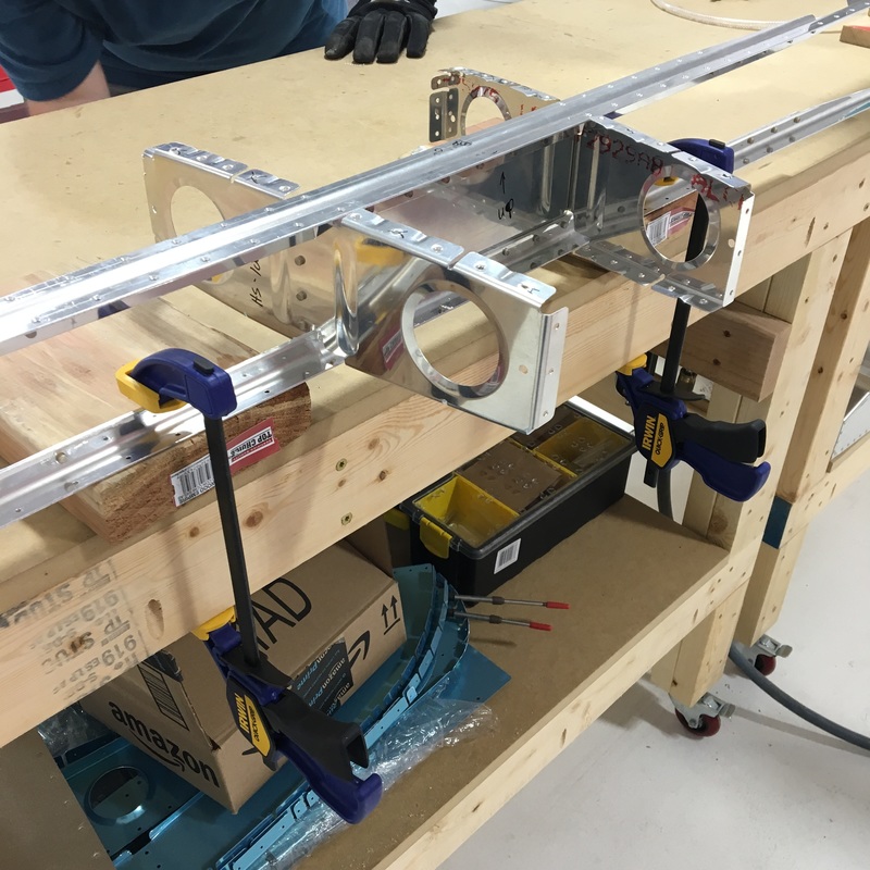 We also worked on solving another annoyance and potential problem we have encountered while riveting - scratching the surrounding metal with the bucking bar. 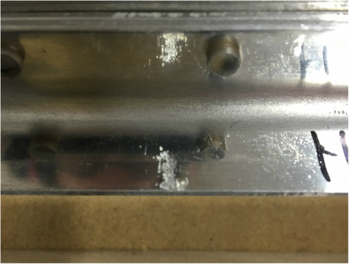 There is very little leeway when you're working with the bucking bar in these tight spaces. It's very hard to see in the picture, but that rivet is less than half an inch above the 90 degree bend. It can be quite challenging to hold the bucking bar so there is enough flat surface to hit the rivet squarely without bumping into anything else. We tried another tip that Mike read online and wrapped the bucking bar with some tape. 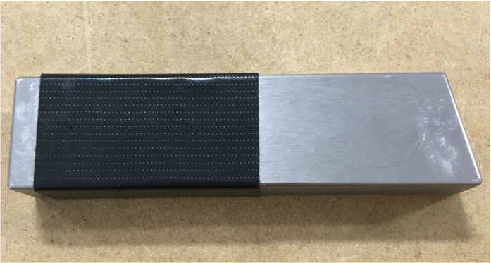 It seems to work very well and let's me position the bucking bar in the most comfortable place without worrying about scratches.
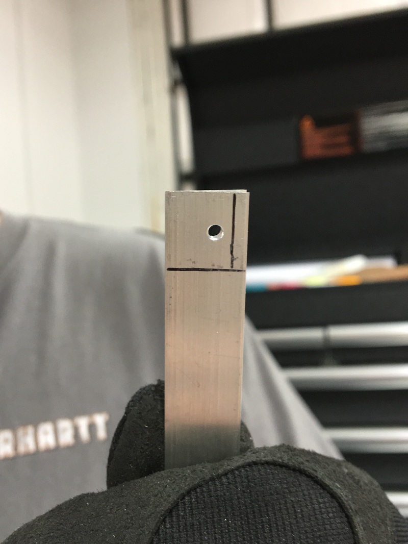
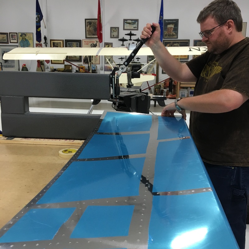
Exciting is not a word I would use to describe the last month of working on the plane. There is always a huge sense of elation when you get to fit everything together...until you remember that you have to drill, deburr, dimple and countersink every single hole in every single piece. The weekend after we got everything put together, Mike spent hours final drilling all of the holes in the horizontal stabilizer skin and a few other random pieces. Some of those pieces were quite difficult to get to, so he got to order a new tool - an angle drill. 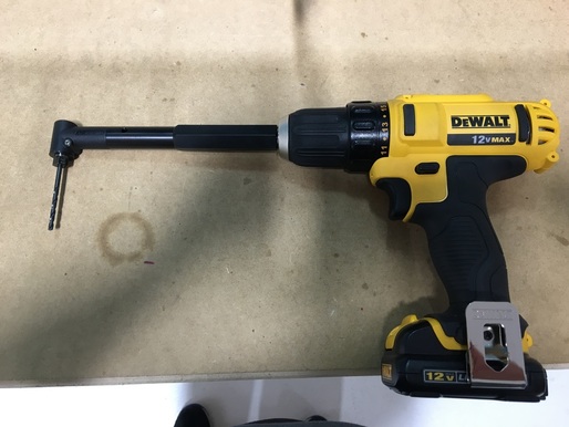 I talked Mike out of the model that cost several hundred dollars and convinced him to get something that fit his existing drill. Considering we used it for about five minutes, I'm glad we were able to reach that compromise. We needed to drill holes into a small plate that connects the two horizontal stringers. The front and rear horizontal spars are directly above and below this plate so there is absolutely no way to get a regular drill into that tight space. After Mike finished drilling all the holes in the skin, we took the whole thing apart. After the excitement of getting the entire horizontal stabilizer fitted together, there is nothing more disheartening than taking everything apart again. When we put the parts together, we grabbed extra bags of clecos as we needed them. Once we took them all out, you could really appreciate the number of clecos we used to put the whole thing together.  In fact, there were so many clecos that the handle on our cheap plastic bin couldn't handle the weight.  We spent the next three weeks completing three steps in the instruction manual. 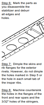 Actually, it took us an entire weekend to complete Step 6. A weekend consisting of three trips to the hangar and 10 man hours of effort. Drudgery is the only word I can use to describe deburring all of those holes. Both sides of each hole had to be deburred, which obviously doubles the amount of work you think you have to do. The ribs are the most annoying because, while you can use the drill to deburr the holes on the outside, you have to deburr the holes on the inside of the flanges by hand. 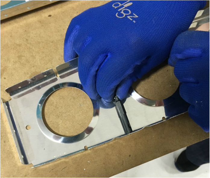 Before you ask, yes we tried the fancy new angle drill attachment, but the diameter of the drill head was too large. That deburring bit is pretty much flat against the web of the rib. It was hard enough to grab onto with the tips of your fingers. After deburring several hundred holes by spinning that bit, your fingers get pretty sore. The skins were much easier to deburr. 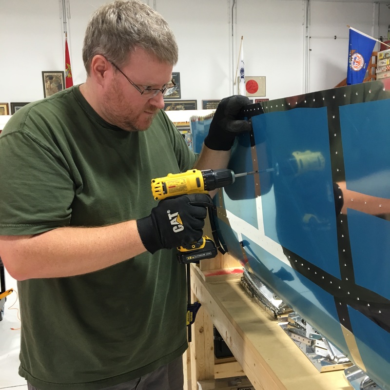 Even so, note the slightly crazed look on Mike's face. This picture was probably taken eight hours into our marathon deburring weekend. I deburred the other skin and figured I might as well count the number of holes in each skin - 250. That's 250 per side, so there were actually 500 holes in each skin. Multiply that by two because there are two skins = 1000 holes. And of course there are all of the holes in the underlying structure, approximately 1000 additional holes. Each of the holes in the skin and skeleton has to be deburred on both sides, so that's 4000 deburred holes. What a way to spend a weekend. The next weekend, we had to dimple all of the holes in the skin and most of the skeleton as well. We used a dimpling die for our hand riveter to dimple the ribs. There are about eight holes on the horizontal stabilizer that don't get dimpled (for some secret reason that's not revealed in this section of the instruction manual) and while we marked those on the skin, we forgot to mark them on the ribs. So, we had to undimple a few holes, which we did by using a flat die that we normally use for riveting. It's not perfect, but it should work. While I dimpled, Mike worked on countersinking the holes in the front and rear spar. This metal is too thick to dimple, but there has to be a recessed area for the skin dimples. Countersinking can be challenging because we don't have any sort of gauge to make sure the countersinks are the right size. Mike dimpled a scrap piece of aluminum that is the same thickness as the skin to use as a gauge. It's not an ideal situation but it's better than nothing. We used the big C-frame dimpler to dimple the skin. It's definitely a two person job so I only got one picture (while balancing my end of the skin - Mike is a good sport when I want a picture). That took another weekend at the hangar. We are finally ready to start riveting pieces together. That's a skill we haven't practiced in several months, so we'll see how it goes.
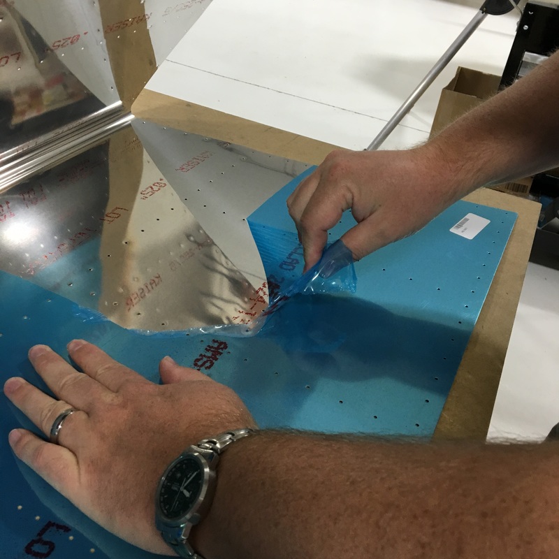
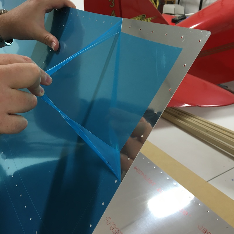
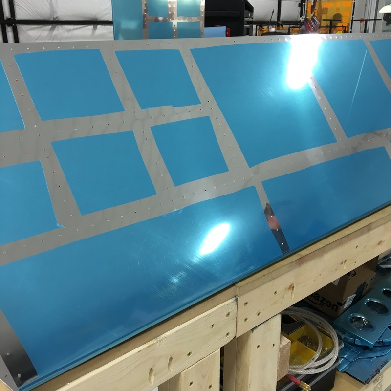
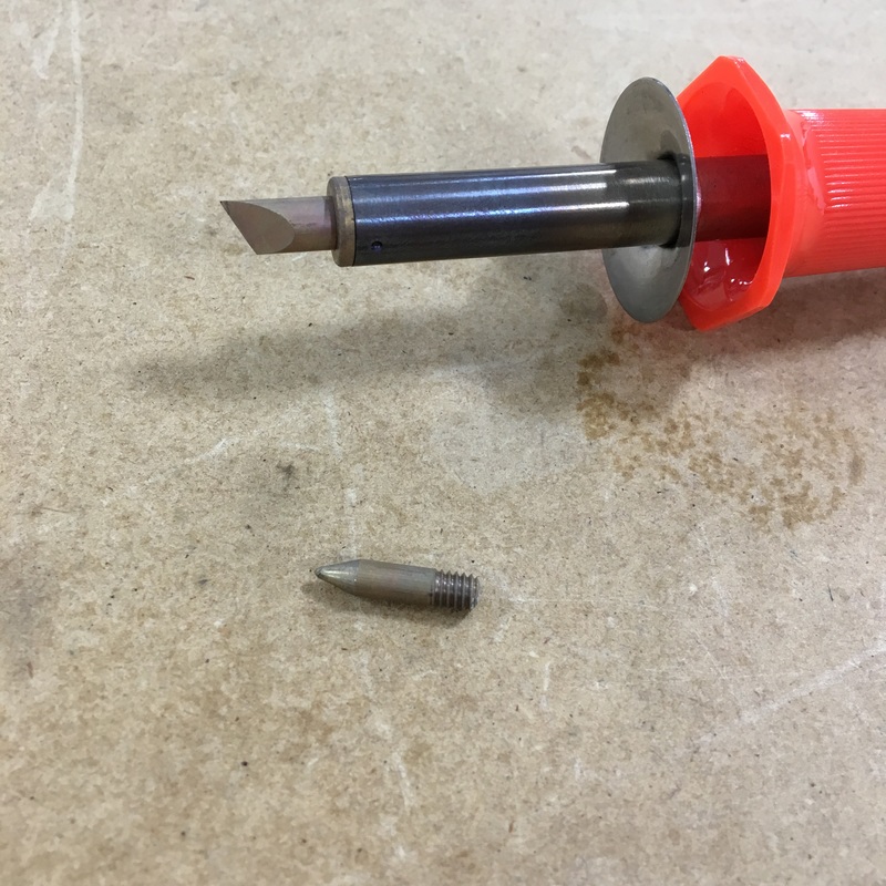
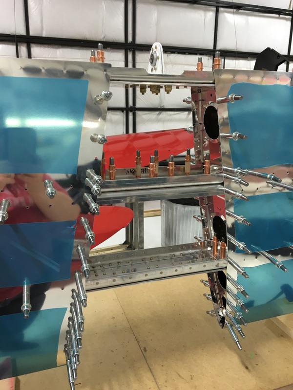
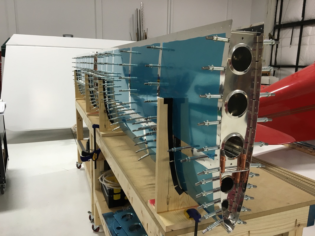
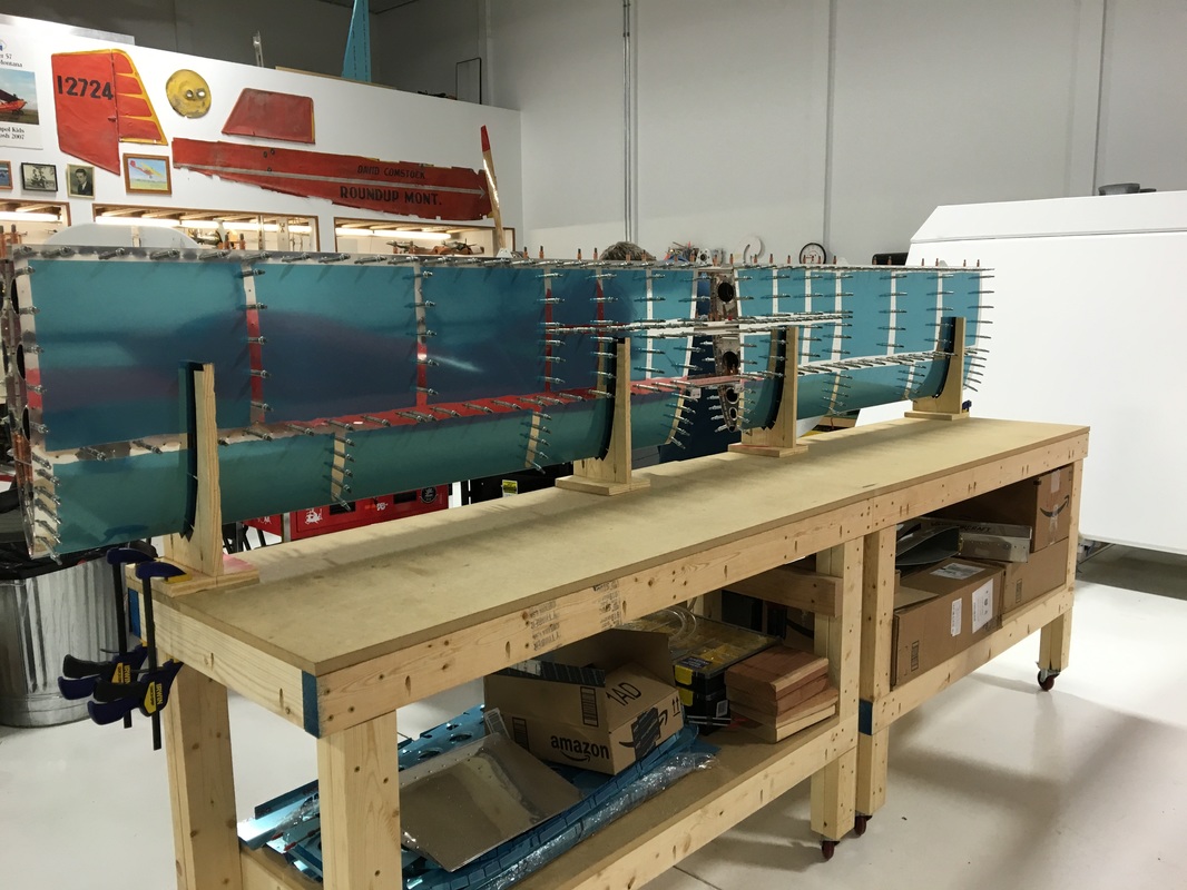
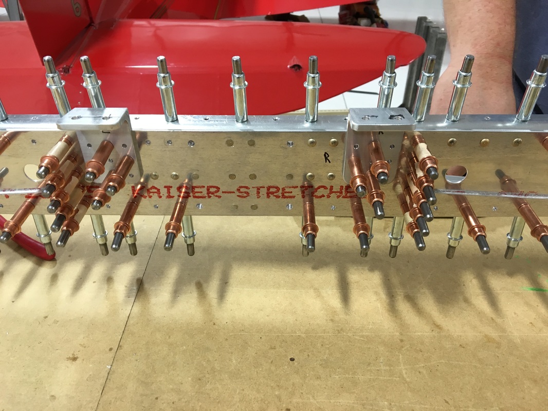
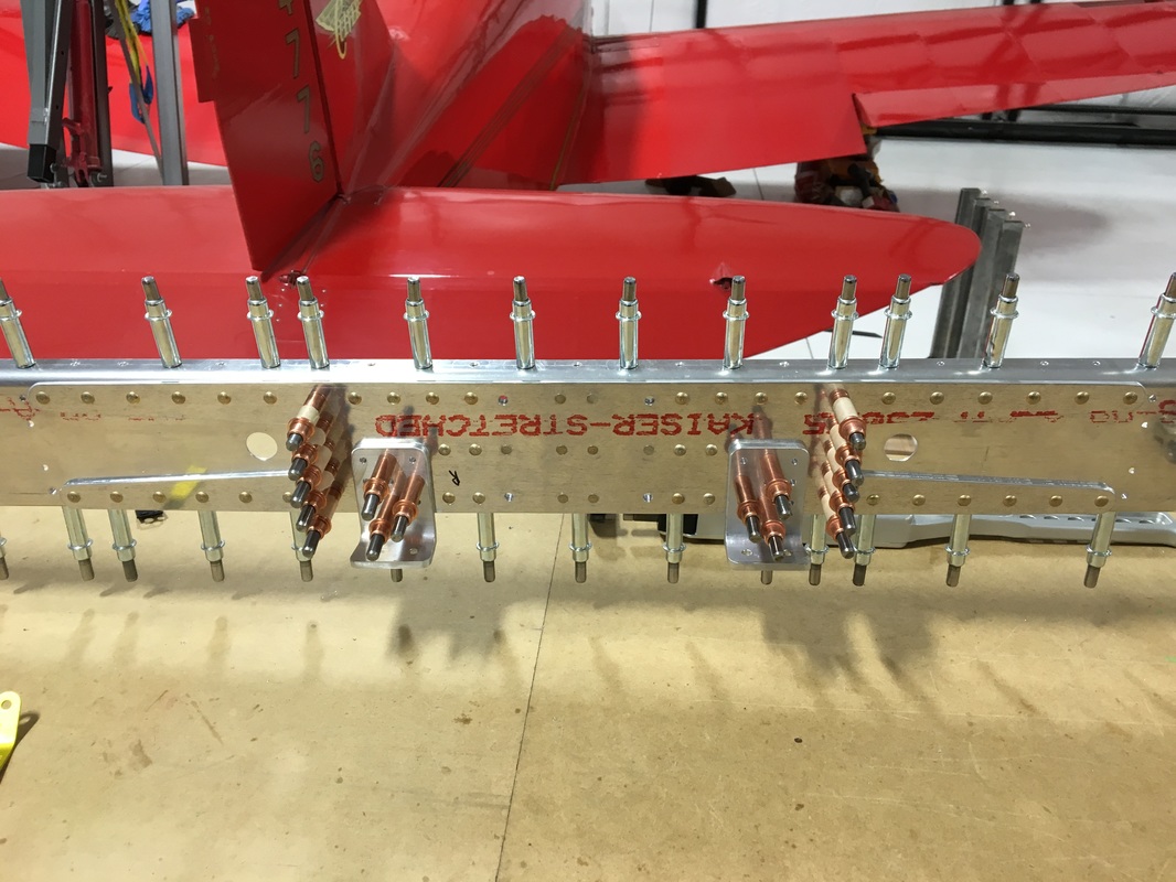
I'm really behind on blogging so I'm trying to get caught up. I'm writing multiple posts today, so if you've just joined me, be sure to scroll down and read Parts 1 and 2 first. Before we could continue, we had to get the horizontal stabilizer skins out of storage and get them prepped. That meant removing the vinyl from the inside of the skins and around the rivet holes on the outside of the skins. We used the same method as before where we scored the vinyl with a soldering iron so we could peel it off in smaller chunks. We experimented a little bit to figure out which soldering bit worked the best and it's definitely the angled bit rather than the pointed one. With all the spars completed, the skeleton and skins prepped, and the cradles fabricated, we could finally start putting everything together! This is always a really exciting part of the build. You spend the majority of your build time working on pieces that you don't know the purpose of and then set them aside for a couple of months. It's fun and surprising to finally see everything fit together. The fun is slightly tempered by the knowledge that this is just the pre-assembly. We will have to take everything apart at least one more time before we actually begin riveting. We started by setting the skins into the cradles. Then we removed the nose ribs one at a time and clecoed them into the skin. The aluminum skins are so shiny that you get these really amazing kaleidoscopic images during assembly. 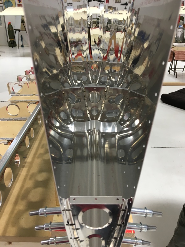 Next, we added the front spar with the attached inspar ribs and clecoed the spar to the skin and the nose ribs. Well, Mike clecoed the spar to the nose ribs because I couldn't reach. 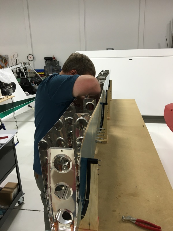 And we finally found out the answers to two mysteries - what is the purpose of the four extra pieces in this photo (which is from April) and why did we have to cut notches into some of the inspar ribs? 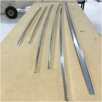 It turns out that those long pieces get put together into two "stringers" which are then inserted into the notches we cut. I have no idea why the stringers are necessary but it's always a relief when you don't have extra parts at the end of the day. Once the stringers were in place, we could finally cleco the skins and ribs together and add the rear spar. We had to open three additional bags of clecos before we were done and the whole thing looked like a porcupine by the end. But it also looks like something that belongs on an airplane. How cool is that!
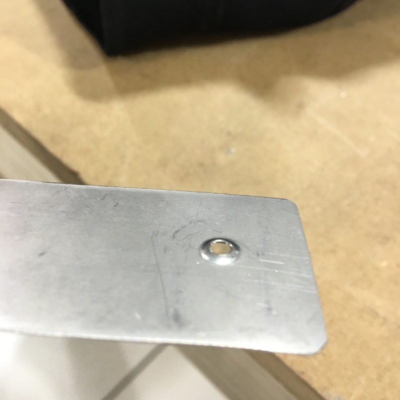
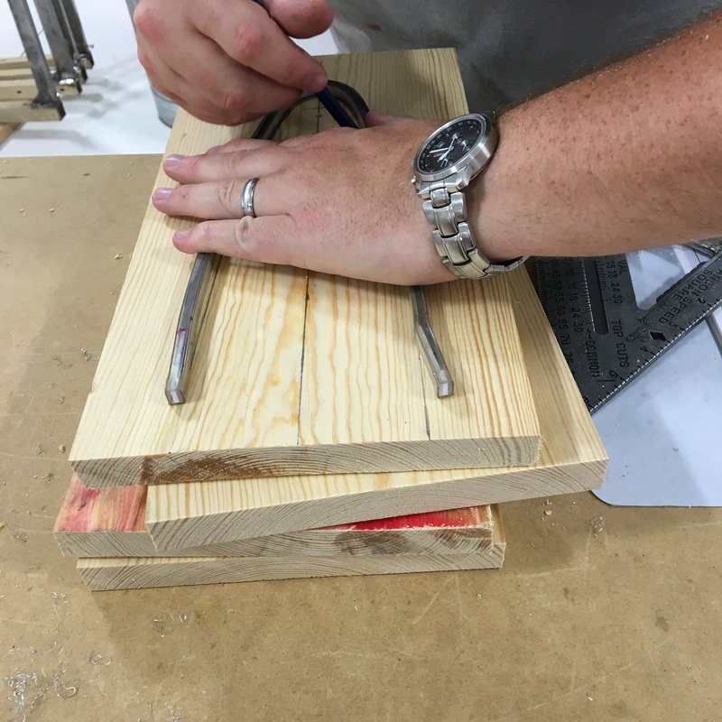
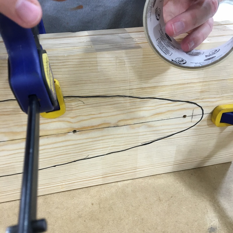
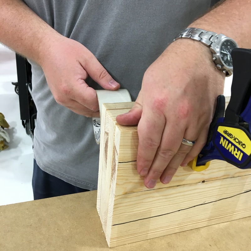
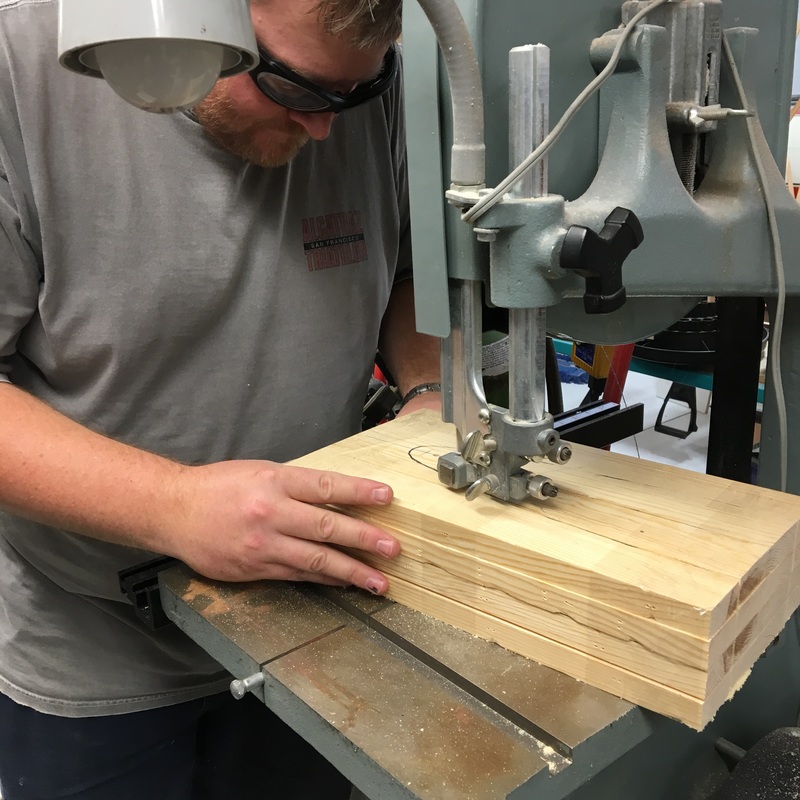
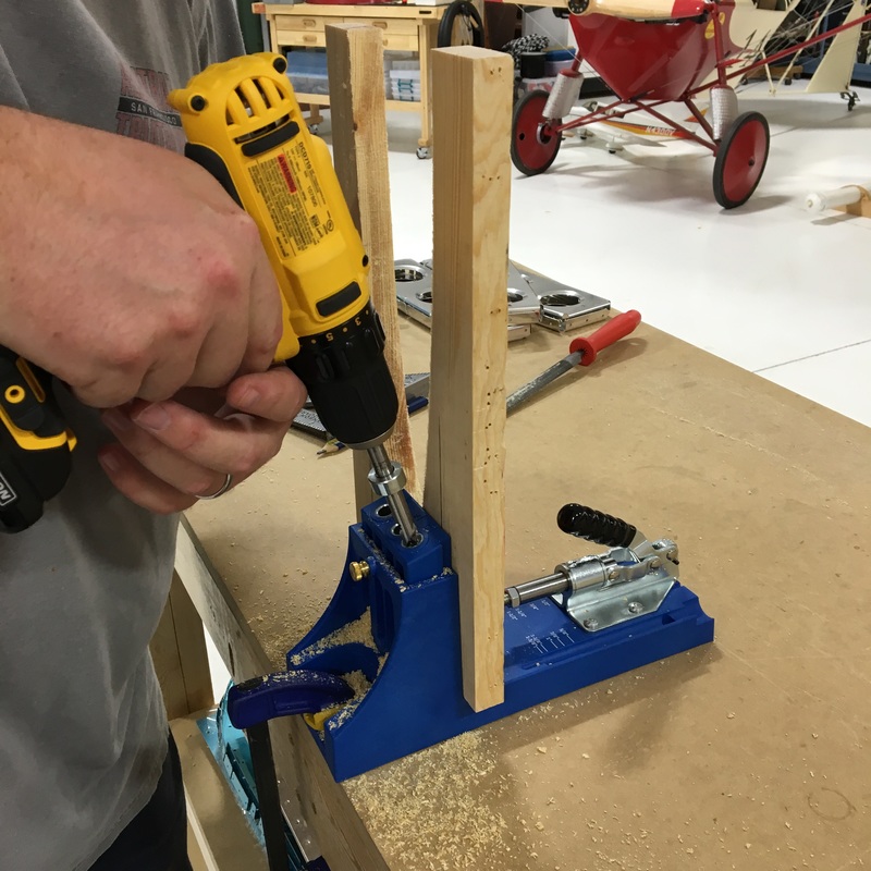
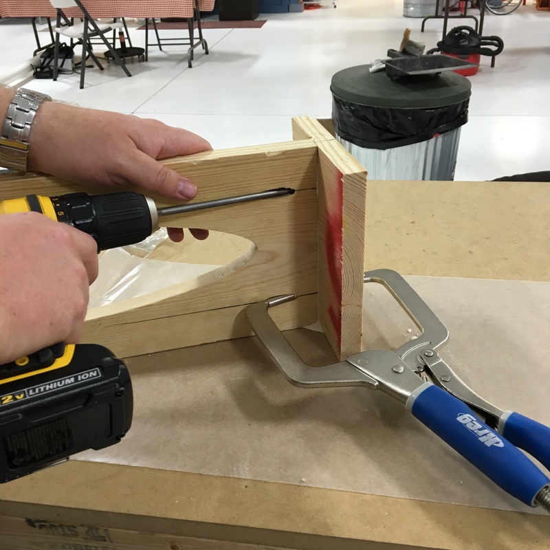
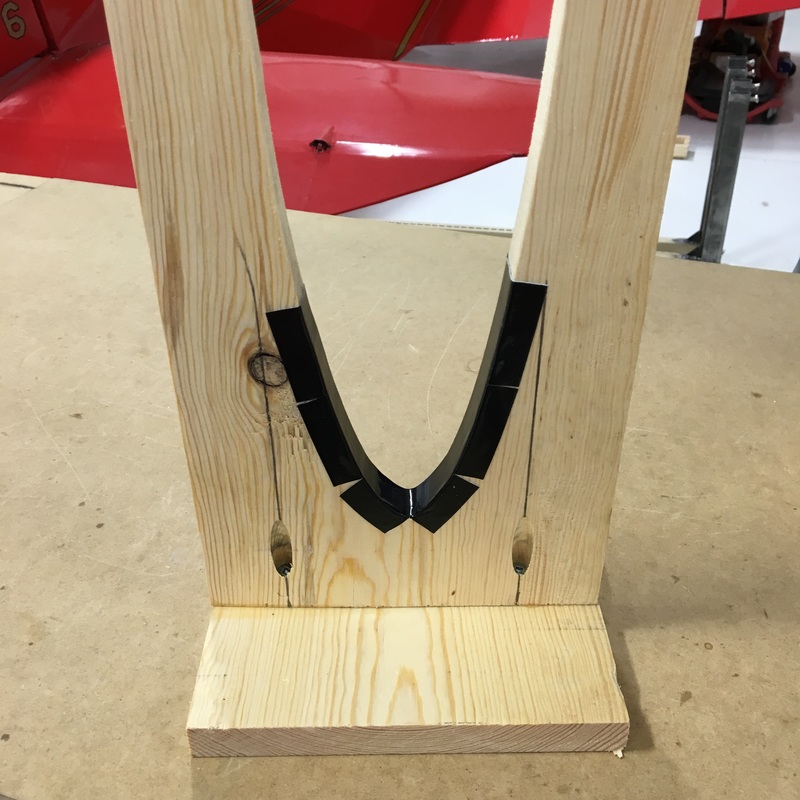
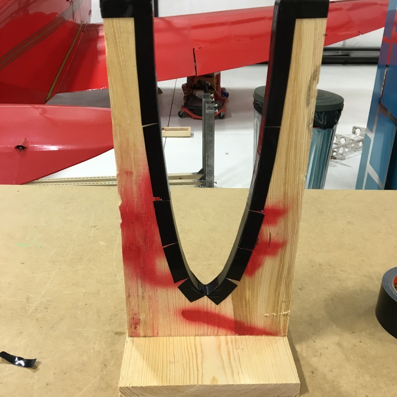
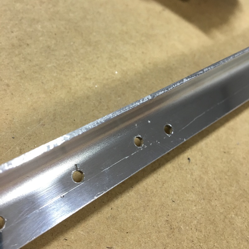
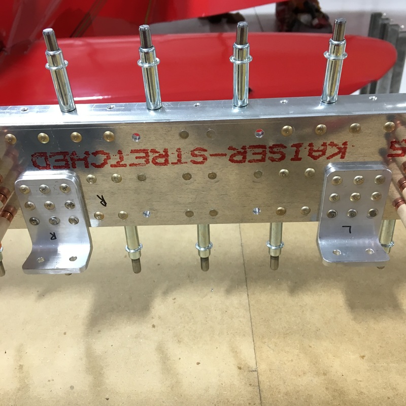
I'm really behind on blogging so I'm trying to get caught up. I'm writing multiple posts today, so if you've just joined me, be sure to scroll down and read Part 1 first. Once the front spar was finished, we started work on the inspar and nose ribs for the horizontal stabilizer - basically all the guts that go inside (The inspar ribs go in the middle between the front and rear spars that we've already completed. The nose ribs go up at the front.) I deburred ribs for two solid hours one day! I didn't take any pictures because you don't need to see every single pile of aluminum shavings I create. While I deburred, Mike had to notch and bend a couple of the ribs for some as yet unexplained reason. I was so busy deburring that I forgot to take pictures of Mike cutting the notches into the ribs. I think he did the cutting with his dremel tool. The instructions told us to bend sections of two inspar and two nose ribs precisely nine degrees. That sort of precision is kind of hilarious considering nothing is exactly straight in the first place. Here is Mike doing his best to create those 9 degree bends. Mike also had to flute some of the ribs so they would lay flat (obviously not the ribs he just painstakingly bent by 9 degrees). While I continued to deburr in the background, Mike fabricated some cradles that we will use when we put all these pieces together. He clecoed an inspar and nose rib together, traced their outline onto some scrap lumber and cut out four cradles. We're totally turning into hoarders on this project and save anything that might be of use later. We used the lumber from the crate the empennage kit came in to make the cradles. Mike also used a bendable ruler to make the template, which I thought was amazing. How have I lived my whole life without realizing that this was a thing? He taped all four pieces of lumber together and cut them out on the band saw. Once they were cut out, guess what I got to do? I got to deburr (also known as file) the edges of the cradles. 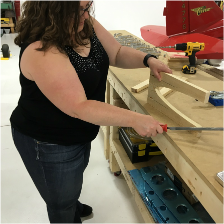 Don't I look thrilled in that picture. You should also admire the beautiful sunburn I got at work earlier in the week. You've may have noticed at this point that Mike has a tendency to make things fancier (i.e. more complicated) than necessary. There is a special tool for everything! With that in mind, you should not be surprised that Mike used his pocket screw jig to put together the cradles. To finish the cradles, we put tape on the edges to protect the skin later. An entire morning of work resulted in four cradles and a stack of ribs. 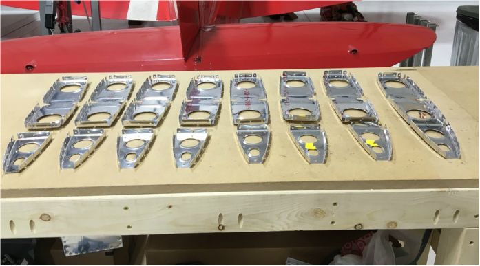 We started to assemble the spars and the ribs, which is when we realized that there were six more inspar ribs that weren't mentioned anywhere in the directions until they were referenced on a diagram. We dug those out, prepped them and finally ended up with a complete horizontal stabilizer skeleton.  I'm just going to admit that I've been pretty terrible about blogging lately. Not to make excuses, but it's a pretty busy time of year for me at work and it's been hard to find the motivation to write. Even though I haven't posted lately, A LOT of work has happened on the plane. I think you'll be pretty amazed when you see what we've accomplished in the past few weeks. I'm going to try to get completely caught up today, but I'll probably have to break this into multiple posts. The last time we talked, we had just received the replacement parts from the mistake we made back in May when we drilled the wrong size holes in the wrong place. Our first step, obviously, was to repeat all the steps required to prepare the replacement parts. That meant more deburring (for me) and modifying the spar caps (for Mike). Once we got all the parts ready, we clamped the spar caps and spar together and drilled the right size holes into the web. In the last few pictures you can see the amount of metal shavings that accumulate when we drilled. Here's a better picture of what the bench looked like when we were done. 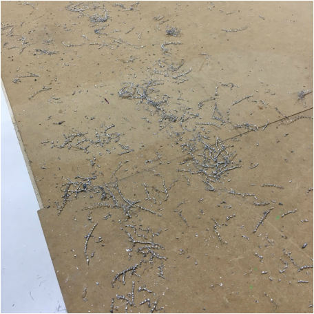 After we drilled the holes, we had to deburr them to remove any metal shavings that were still attached. To do that, we use a special deburring bit for the drill. The bit doesn't enlarge the hole, it just scrapes off any metal that shouldn't be there. Here are some great pictures of a hole (the hole in the middle) before and after deburring. At this point, we were finally where we would have been if we'd read the directions properly the first time. Next, we had to rivet on the doubler, which provides extra strength to the spar. This the diagram that we were using... 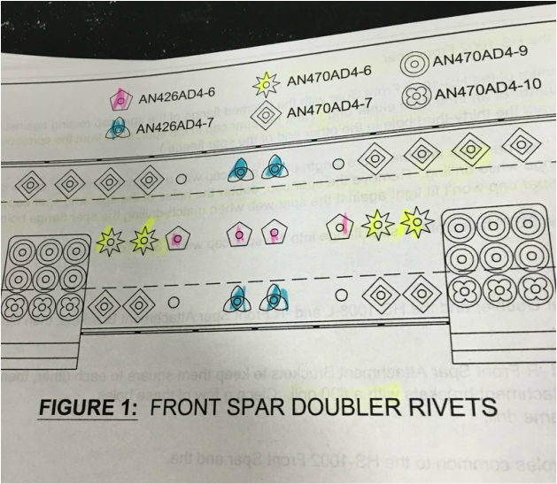 Yes, there are six different sizes of rivets on that diagram. You can see where I started to highlight each size so I could mark the clecos with tape. 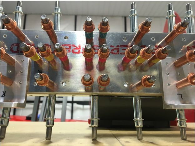 In the bottom corners you can see the brackets that Mike fabricated ages ago. Here's a better picture of the entire double clecoed to the spar. (Side note - can any of my English teacher friends help me figure out the verb conjugation for cleco? I'm totally making it up as I go.) 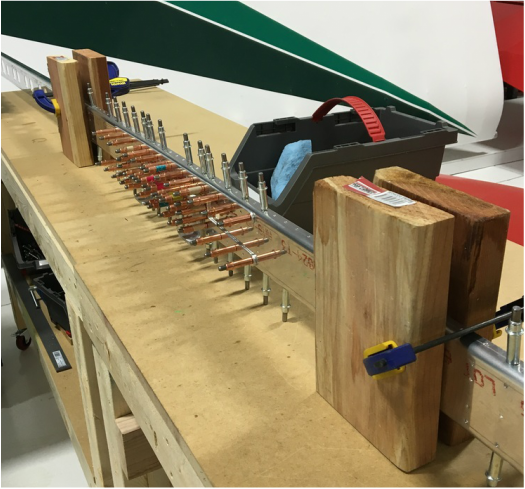 The silver clecos along the top are holding those spar caps in place, which made riveting the doubler in place more challenging. We clamped the spar in between some leftover chunks of wood so we could keep the whole piece upright and semi-stable. Then we just had to follow the diagram and use the right rivets in the right place. We mostly used the squeeze riveter but the squeezer couldn't reach some of the rivets on the brackets. We had to buck those and let's just say that we were a little bit rusty at that particular skill. We got them all done, but it wasn't always pretty. On the left, you can see where Mike slipped on the bottom middle rivet and one side got flattened. On the picture on the right, you can see where I slipped on the bottom middle rivet and gouged the heck out of things. One mistake per bracket, in exactly the same spot, so at least we have a matching set. And with that, we were done with the front spar, at least for the moment. 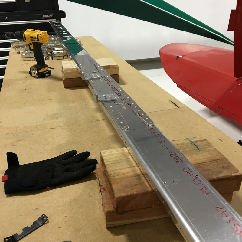 |
AuthorThe supportive spouse's guide to building an airplane. Archives
May 2017
Categories |


 RSS Feed
