|
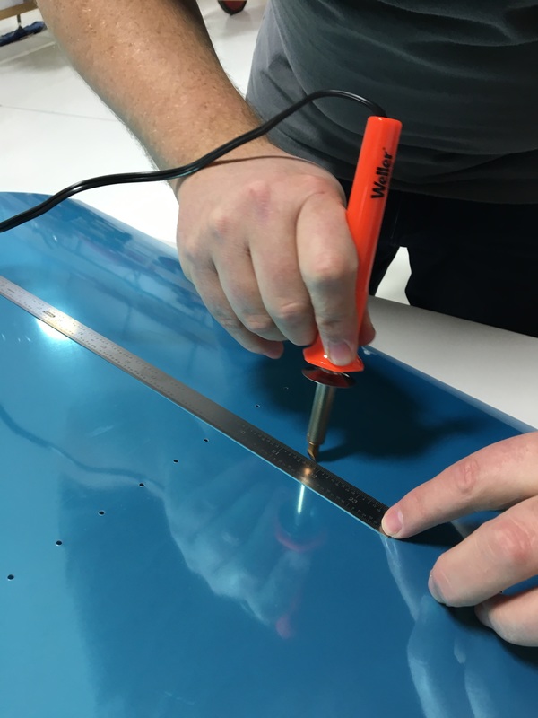
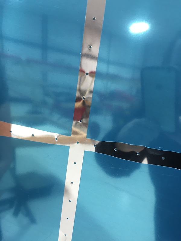
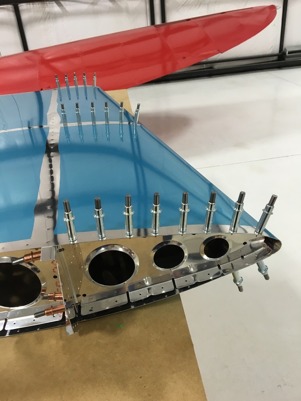
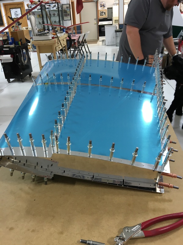
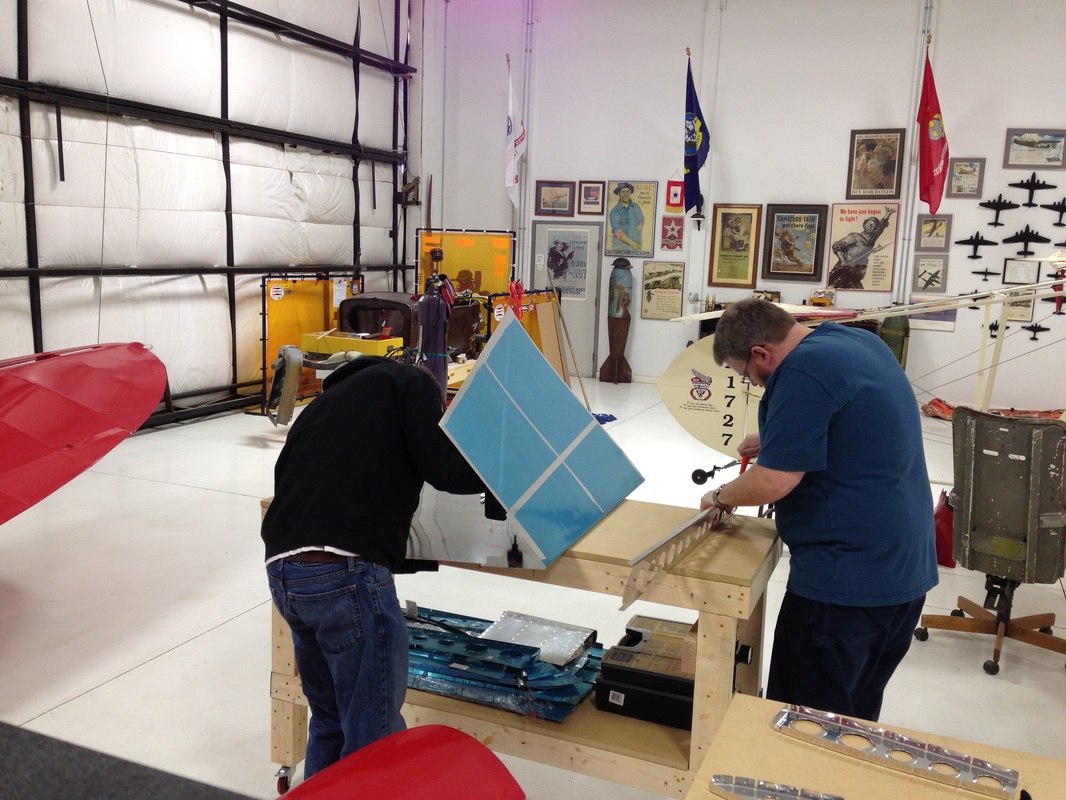
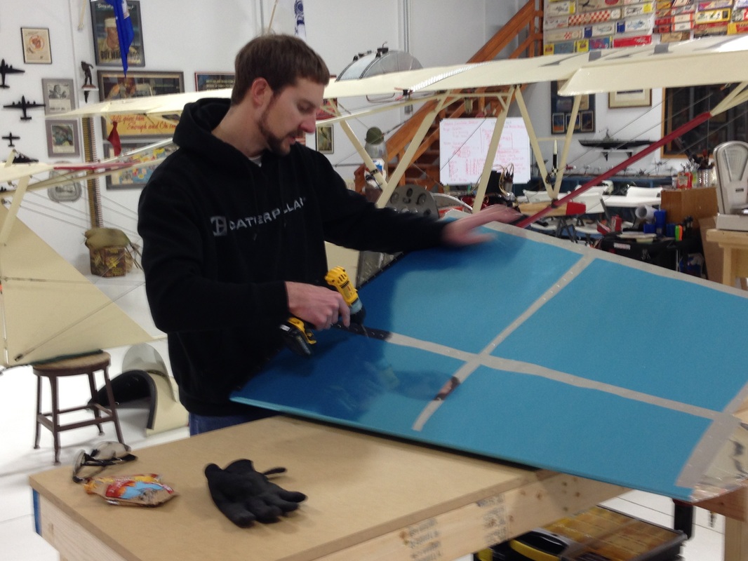
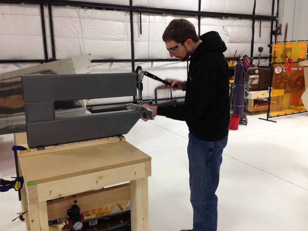
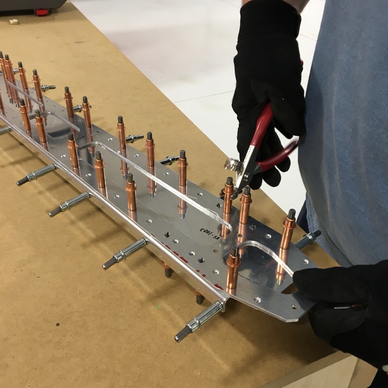
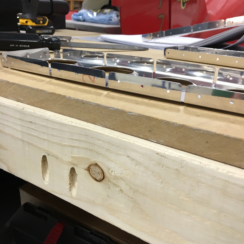
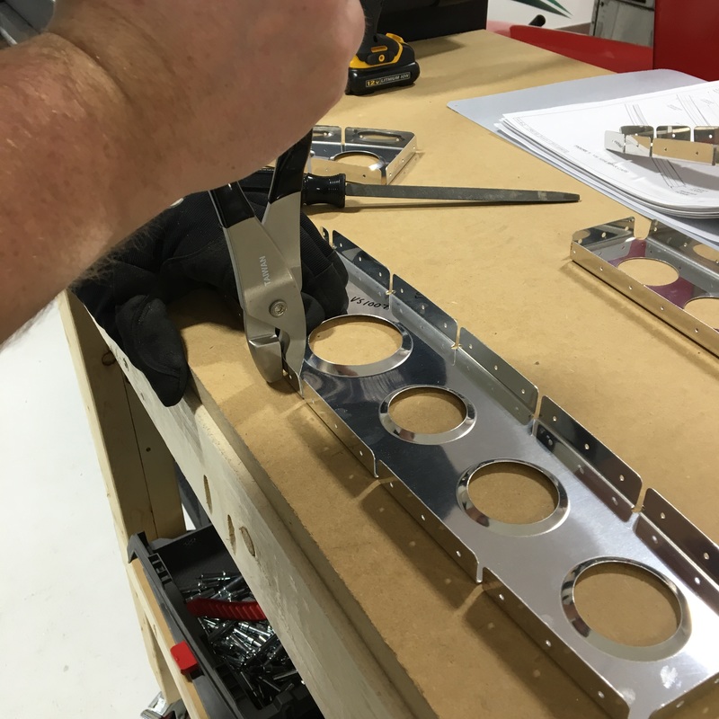
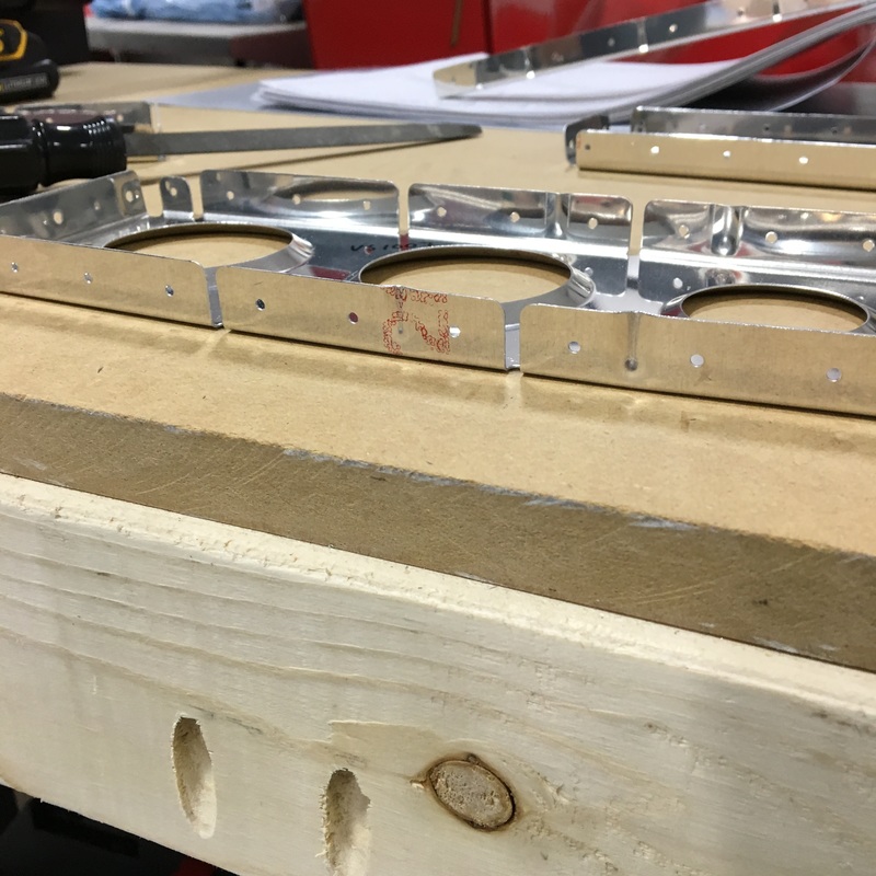
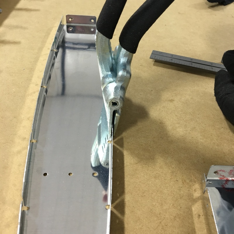
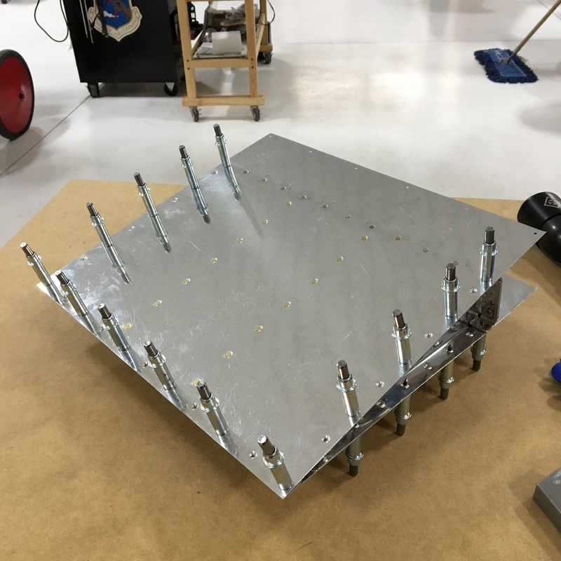
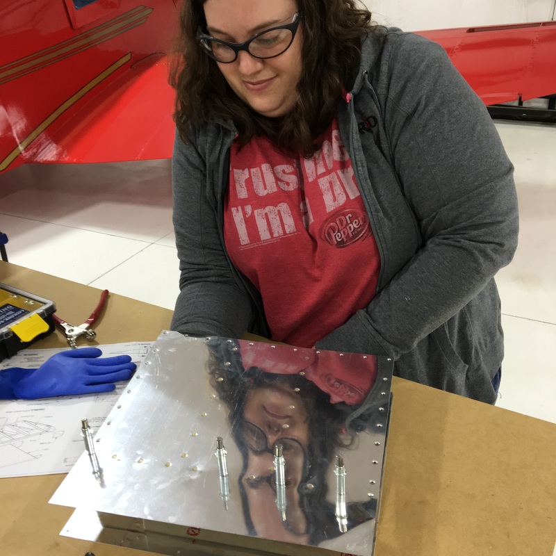
I've learned a big lesson about building airplane this week - sometimes it's hard to see that you're making progress. We've been continuing to work on the vertical stabilizer and since my last post we've put the whole thing together...and taken it all apart again. Apparently, putting things together and then taking them apart so you can put them together again is a big part of the build process. Now, I have to be honest and say that Mike did warn me about this. I believe he said that we will basically build our airplane four times before we are done. It can be a little disheartening to put in several hours of work to end up with the same pile of pieces you started with days ago. But, I suppose it's all progress and every single step gets us closer to a finished product. You might remember that at the end of my last post, we had finished putting together the guts of the vertical stab. I don't think that "guts" is an approved airplane term but I have no idea what else to call it. (OK, I just looked at the build manual and the correct term is actually skeleton.) Here's a little reminder about where we will be starting this week's adventure. 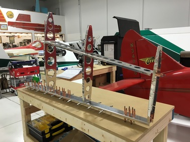 The skeleton of the vertical stabilizer. Our next step was to fit the skin over the skeleton that we had constructed. The skins are the thin sheets of aluminum that make up the outside surface of the plane. The skins come preformed into the final shape they will take on the plane, so they tend to be big and kind of unwieldy. Like the rest of the parts, the skins are also covered in blue plastic to protect the surface of the metal. One most of the other airplane parts we completely remove that blue plastic before we begin working. Since the skins are so easy to scratch, we decided to leave as much of the protective film in place as possible. On the outside of the skin, we removed only a thin strip of plastic around the rivet holes. We used a soldering iron to melt the plastic and isolate the sections that we wanted to remove. The picture below also illustrate an interesting difference between our approaches to this particular task. On the left, you can see Mike using a straight edge so he can score a perfectly straight line in the plastic. On the right, you can see Mike's perfectly straight lines (running vertically) and the wavy lines (running horizontally) where I decided that was a massive waste of time and decided to do it freehand. Oddly enough, prior to this I've been the person obsessed with getting things just right and Mike has just wanted to get things done. We also had to remove all of the protective film from the inside of the skin so we could put the whole vertical stab together. I didn't get any pictures of that process, probably because I was busy swearing at that stupid blue plastic. Let me just tell you that removing big pieces of that protective film is really, really hard. After a lot of frustration and not much progress, we finally wised up and used the soldering iron to divide the inside surface into smaller pieces that we could remove with much less difficulty. Our next step was to fit the skin onto the skeleton (that was a really creepy sentence to type). Again, that turned out to be more challenging than we expected. As I mentioned, the skin is preformed into (roughly) the right shape. The trick is that you have to get all of those little holes you see punched in all the parts to line up just perfectly. The skin of the vertical stab is formed into a big V-shape with straight sides, but the ribs on skeleton are curved. The hardest part to line up was at the front of vertical stab, at the point of the V. After some experimentation we figured out how to make everything line up but we did manage to scratch the inside of the skin quite a bit. Oh well, no one will ever see that once we have everything riveted together. We then proceeded to use about 200 clecos to hold the whole thing together. BTW, if you want to strengthen your hands, buy yourself 200 clecos and a set of cleco pliers. 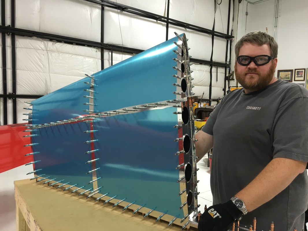 For a moment, it really looked like an airplane! Then...Mike took it all apart. See, the thing is that even though the kit comes prepunched with all of those little rivet holes, the holes aren't actually the right size. They are all just slightly too small and have to be "final drilled" to the correct size. Mike explained why the make the wholes to small but I won't go into that right now. Then, once all the holes are drilled to the correct size, they all have to be deburred. And all that work completed exactly two steps in the construction manual. 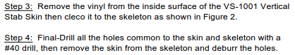 After reading that, I also just learned that the annoying blue plastic film is correctly referred to as vinyl. Finally, all of those holes on both the skin and the skeleton have to be dimpled so that all the pieces sit together properly. You might remember when I talked about countersinking pieces in a previous post. Dimpling is a very similar process, except the pieces of metal are much thinner so you don't have to use a drill to remove the excess metal. Instead, you use a dimpling die to press a little divot into the surface of the metal. This is where the head of the rivet will sit so that it's flush with the surface. Mike's friend, Keith, helped out with the build that day so I have to admit that I can't provide a lot of details on how it was done. I'm sure I'll get to help with it at some point in the future so I'll talk more about when that happens. Here are some pictures of Mike and Keith at work. At the moment, we are back to a pile of pieces on the workbench. There's a few more hours of work to be done before we put the whole thing together (again) and rivet the skin into place. 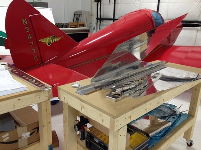 Looking less like an airplane. Also, a nice bonus shot of the Culver in the background. New Vocabulary:
Skeleton - the inside, structural part of the airplane that you don't see Skin - the outside surface of the plane that you do see Final Drill - drilling all the holes to the right size Vinyl - the protective blue plastic that covers every since piece of the plane Dimpling - putting a small divot in sheet metal so the pieces will sit together properly and the rivet head will be flush to the surface
1 Comment
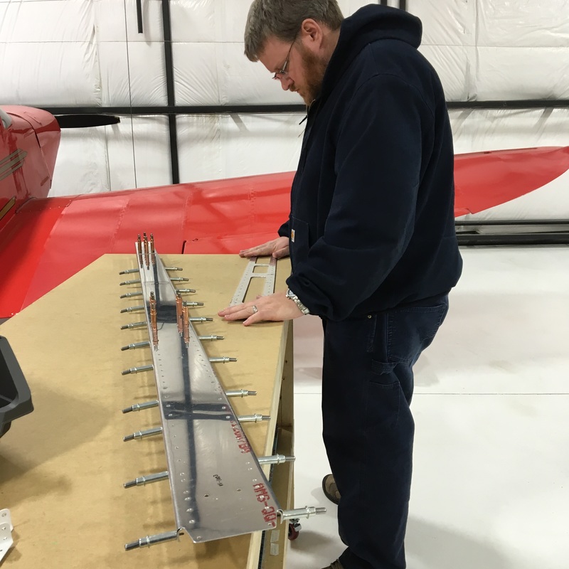
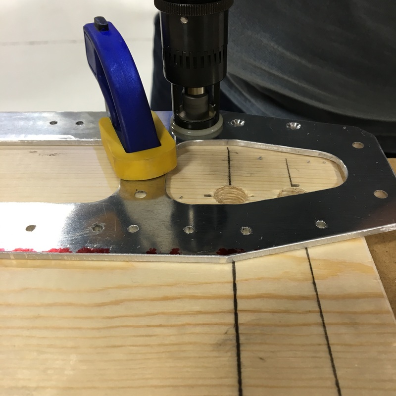
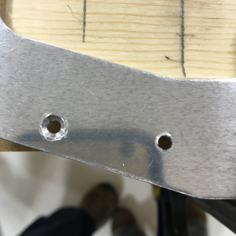
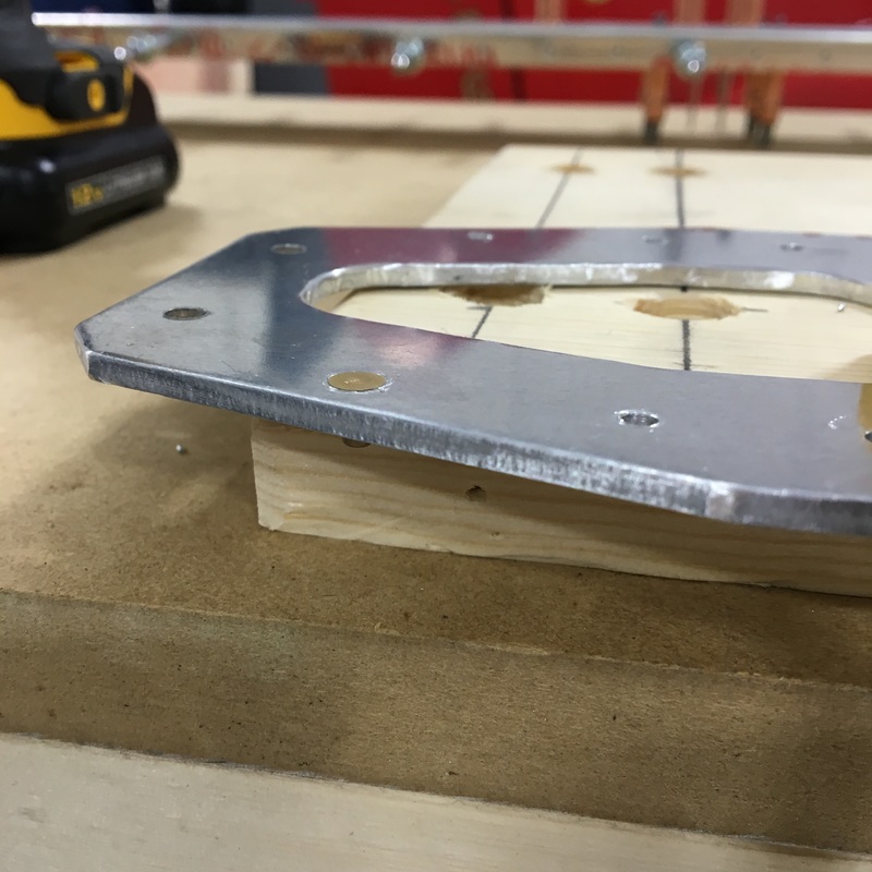
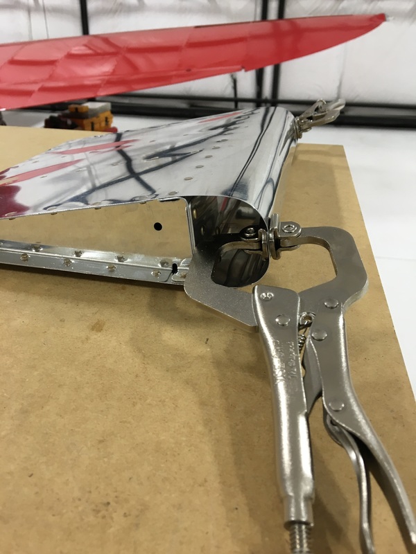
This week we started building the airplane! Just typing that sentence is exciting (and a little bit scary). Mike has been dreaming of this project for years but this is still pretty new for me. It completely astounds me that you can build an airplane from scratch. The building starts with the vertical stabilizer, which is part of the empennage (or tail section) of the plane. (I'm so proud right now that I spelled empennage right on the first try!) The vertical stabilizer (or vertical stab if you want to sound knowledgeable) is the fin that sticks up on the tail. The instruction manual calls this section 6, which I don't understand because it's the first part of the airplane that you build. 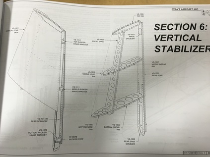 We started by putting together the rear spar - the straight upright section you see in the picture above. A spar is the load bearing portion of the aircraft, so the rear spar is made up of a bunch of different parts including a thick reinforcing piece of aluminum. This reinforcing piece was a lot harder to deal with than the other parts. In the picture below (upper left), you can see Mike trying to remove a bow that was left over from the manufacturing process. The spar is the long piece on the bench with all the clecos in it. Eventually, the spar will abut another section of the tail, so all of the holes need a countersink so the rivets sit flush to the surface and don't rub against the other pieces. Mike used a special drill bit (also called a countersink) to remove some of the aluminum and create a hole for the head of the rivet to sit in. Below (upper right) you can see the countersink Mike drilled out on the left hole. In the bottom left picture you can see how the head of the rivet sits flush with the surface of the metal. Once that was done, that reinforcing pieces is held in place with clecos. FYI - the different color clecos indicate different size holes. Holes with copper clecos are bigger than holes with silver clecos. (I would also like to acknowledge that I have no idea if I'm using the word "countersink" correctly. It seems to be a noun, a verb, and a tool all at the same time.) Once that was done, we spent the rest of our evening prepping the other pieces for assembly. Prepping pieces involves lots of steps: 1. Locate all the pieces that you will need for the next step. This involves digging through boxes and piles of pieces trying to find something labeled VS-1005. You might remember that when we unloaded the crate and inventoried the empennage pieces, there were some groups of parts that were labeled as subkits. During the process of pulling pieces for the vertical stab I realized that those subkits mean absolutely nothing! The parts that you need for a single step are likely found in 2 or 3 different subkits. I even had to pull out the inventory list again to locate where we had stored some of the pieces. This was the point when I realized that the VS I read over and over on the inventory list indicates pieces of the Vertical Stabilizer. 2. Remove the protective plastic film from the pieces. The label that identifies each piece is stuck to the plastic so you have to be write the number of the pieces with a marker. 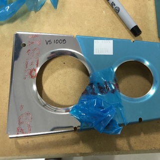 3. Deburr all the edges. We are still experimenting with methods of deburring - so far we've tried three. My favorite so far is using a regular old file to smooth the edges. That seems to work best with long, straight edges. The other method I've personally tried involves using a special deburring tool. The tool has a sharpened blade that you use to shave off a very small sliver of metal. This head swivels so it's really good for curved or oddly shaped edges. Mike has also used a deburring wheel that he attaches to a angle grinder. It's basically just a tiny, fancy grinding wheel. We refer to the deburring process as "making glitter" because you end up creating a small, sparkly pile of aluminum shavings. 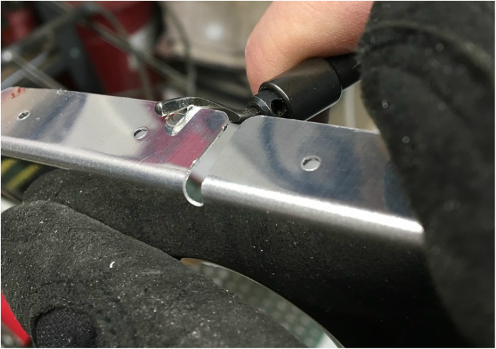 4. Straighten the piece. When they form the sheets of aluminum in the parts, things can get a little wonky. The most common thing we had to do on these pieces is flute some of the edges. You use special fluting plier to put little bends into the flange (the short parts that stick out at a 90 degree angle) so that everything sits flat again. In the series of pictures below you can see the process. Sometimes you also have to bend the flange and return it to the proper 90 degree angle. 5. Put the pieces together with clecos. This is the best part because you can actually see that you're making progress. 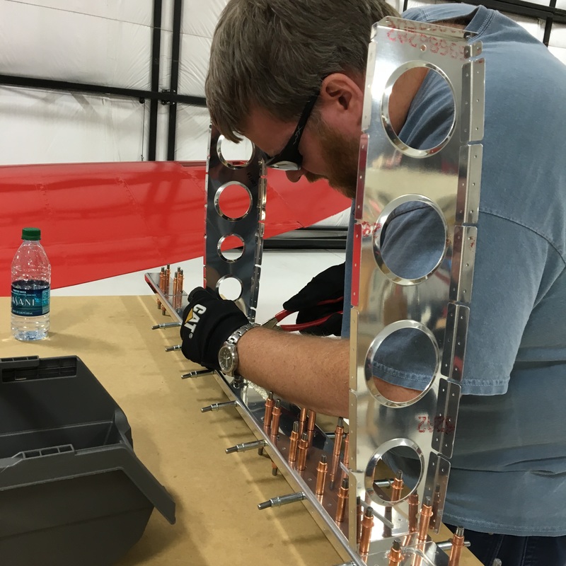 At the end of the night, we actually have something that looks like it belongs on an airplane!  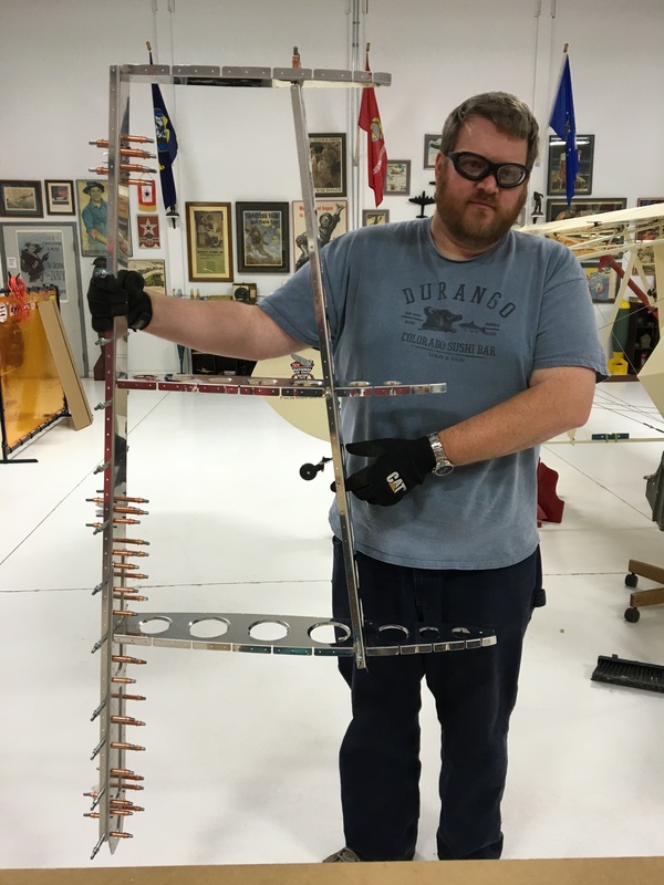 New Vocabulary:
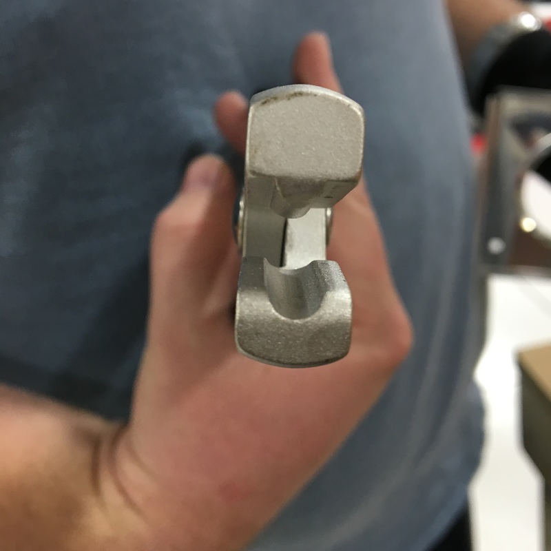
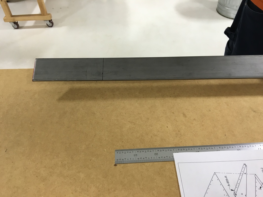
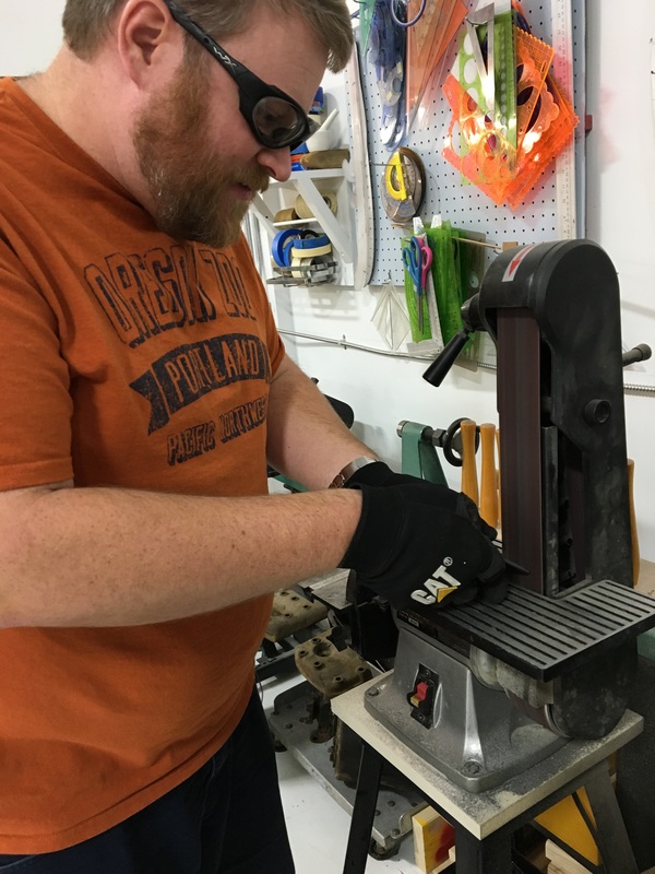
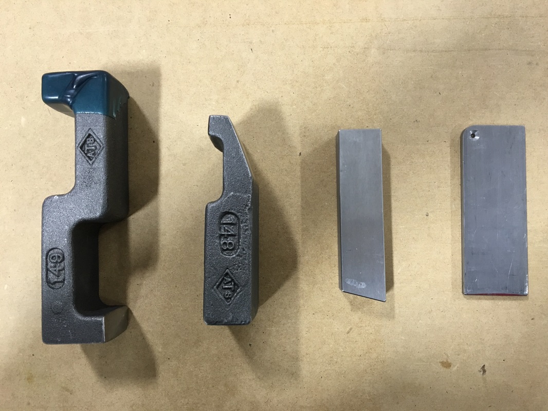
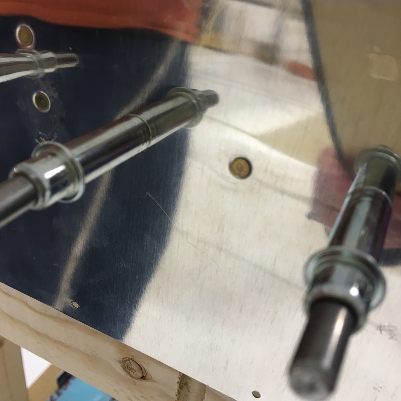
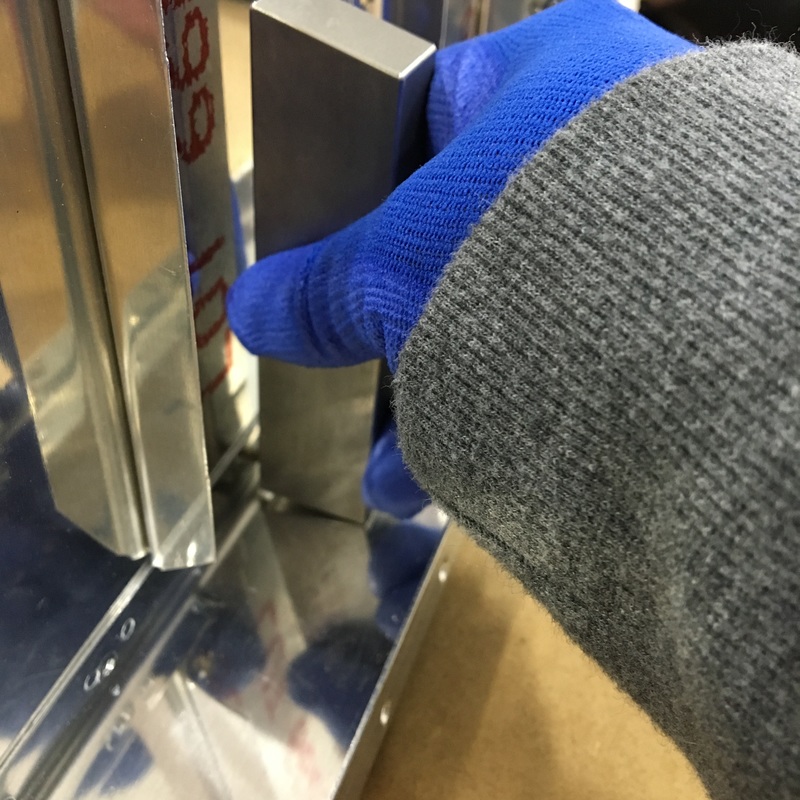
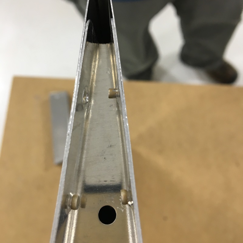
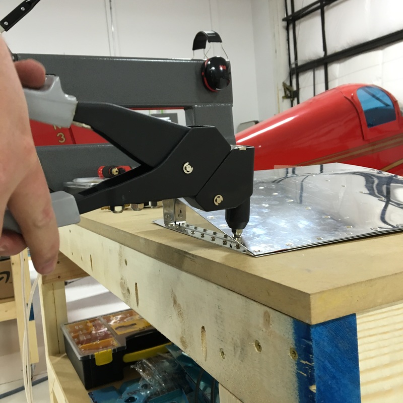
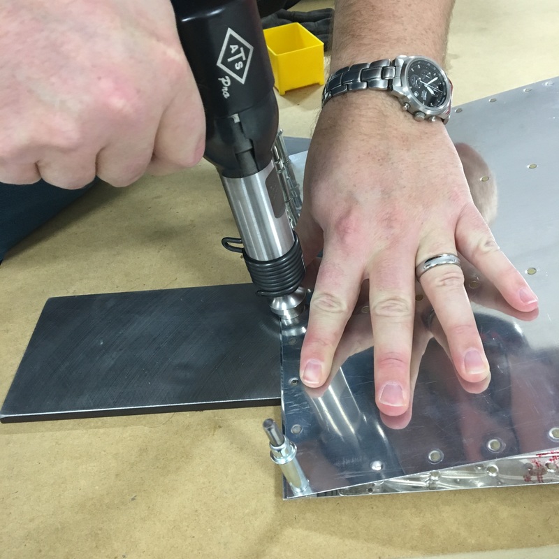
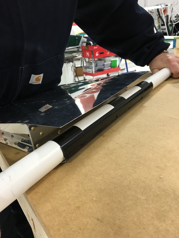
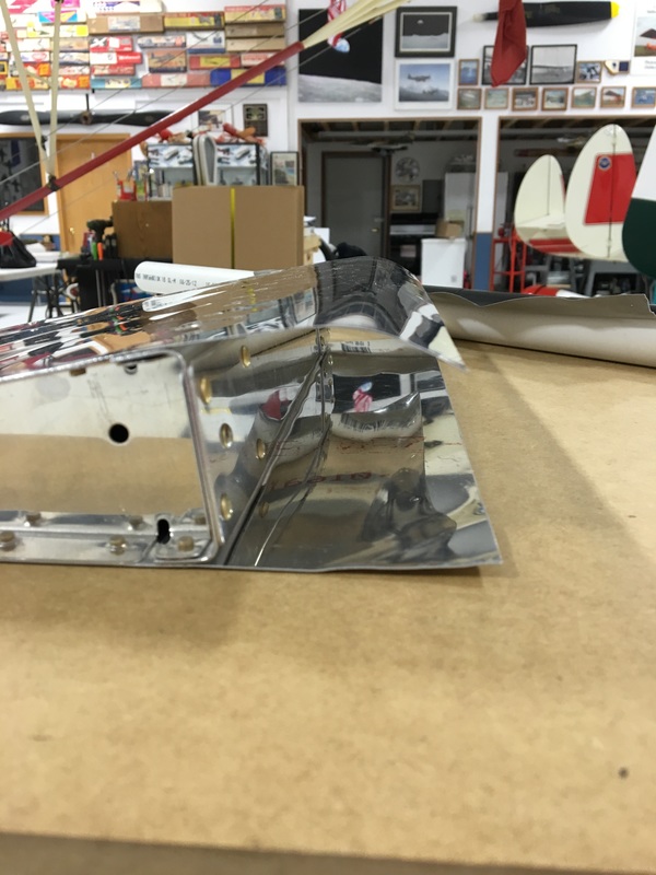
Vertical Stabilizer - the fin that sticks up on the tail of the airplane Spar - a load bearing part of the plane Countersink - making a funnel-shaped opening at the end of a hole; allows the head of the rivet to sit flush with the surface Fluting - making little bends (flutes) in a material; subtly alters the shape of the part to remove bows from the manufacturing process Flange - small section that sticks out and is used to fasten pieces together Progress on the plane has been slow over the holidays. Mike is really eager to get started on the plane but we spent a couple of weeks working on one final practice kit. There are about a thousand different skills that we'll be using when we start our actual build. These kits help us figure out how to use the tools and work out any kinks in our process before we touch the actual (expensive) airplane parts. This time we were practicing a section of control surface, which is a fancy way of describing the moving flaps on the wings and tail. I think we were working on an aileron (the section on the back side of the wings that moves up and down). When we worked on the phone stand kit, we did squeeze riveting where we used big pliers to manually squish a rivet into the shape we want. On this kit, we also got to buck rivets and use pop rivets. Bucking rivets is kind of fun but also more challenging than I expected. It requires using a pneumatic rivet gun smash a rivet into a bucking bar (basically a big, solid piece of metal). If you've done it right, the manufactured flat head of the rivet will sit flush against the metal and the shop head (the part of the rivet you smashed) will be the right shape to hold the two pieces of metal together. You can see an example of a perfect shop head in the picture. You can also see why we have to dimple the metal before riveting so that everything fits together correctly. 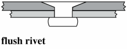 Mike did most of the prep work on this project so I got to miss out on the super exciting process of drilling and deburring holes. I'm going to have to figure out a way to make all that prep work more enjoyable because it probably takes twice as long to prep the pieces as it does to actually put things together. Mike also had to fabricate a special modified bucking bar that is narrow enough to fit into tight spaces. It also has a hole drilled into it that you can use to dimple metal if you're working in tight spaces where you don't actually have enough space to use a dimpling tool. Mike says this is called a countersink. We used clecos to hold the pieces together and then bucked a bunch of rivets. For the most part, Mike ran the rivet gun and I held the bucking bar. I like bucking rivets because it's kind of an art. You have a bunch of different bucking bars to choose from and you have to try to find one that will fit into the space where you are working and hold it just right so you smash the rivet evenly. The bucking bars are pretty heavy so they will smash the rivet as they rebound and hit the rivet. We remove one cleco at a time and put a rivet in every other hole. Then we can go back and make a second pass to finish riveting all the holes. The aileron is shaped kind of like a sideways tear drop. It's curved at the front and comes to a point at the back. Putting everything together was kind of like making a sandwich where the metal skins make up the bread and the filling is air and other support structure. The first side we riveted was pretty easy but once we put the second skin on things got really cramped. The space between the two skins is only a few inches at the widest point and I had to try to hold a bucking bar up against a rivet I couldn't see. Below you can see me with my arm wedged inside the structure. On the trailing edge (the tip of the tear drop) we only had about a quarter inch between the two sides. We tried to use the thin bucking bar that Mike made earlier but it just didn't have enough heft to smash the rivet...so we improvised. We ended up using the rest of the 3 foot steel bar that was left over earlier. I was able to press on the end of the bar and we could get enough leverage to create a shop head, although it wasn't very good. We tried the same approach with the rivet on the opposite skin but there was just no room (see the upper right picture below). After trying several different approaches we decided to just use a pop rivet in that corner. It wasn't the greatest solution but we were pretty frustrated at that point. Once the sides were riveted, Mike was able to finish the trailing edge. The final step was to finish the leading edge (the curved part of the tear drop). You can see in the picture above that the two skins are completely flat. We had to bend the front edges so we could join them together. This was a very high tech process involving a length of pipe and some duct tape. Basically, you tape a pipe to the edge of the skin and roll everything up to create a curve. It was really easy to bend the skins using this technique. Actually, this fact is kind of scary because I can see how easy it would be to accidentally bend a really expensive pieces of aluminum. Once the two skins were bent, we were able to pop rivet the two edges together. 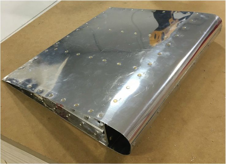 The finished project. It was exciting to see a finished product that actually looks like it belongs on an airplane. It also means that practice is over and it's time to start work on the actual plane. We pulled the pieces that Mike will need first and now the building can begin!
|
AuthorThe supportive spouse's guide to building an airplane. Archives
May 2017
Categories |


 RSS Feed
